Piping and Connections
104 CLCH-SVX07K-EN
Note: Do not drain the steam mains or take-offs through
the coils. Drain the mains ahead of the coils
through a steam trap to the return line.
7. Ensure overhead returns have 1 psig of pressure at the
steam trap discharge for every 2 feet of elevation for
continuous condensate removal.
Water Coil Piping
Type 3W, 5A, 5W, D1, W, UW, TT, P,2, P4, and P8 water coils
are self-venting only if the water velocity exceeds 1.5 feet
per second (fps) in the coil tubes. Type D2, UA, UU, 3U, and
WD water coils are self-venting only if the water velocity
exceeds 2.5 fps in the coil tubes. See the unit submittals for
coil water velocity. If the water velocity is below these
minimums, vent the coil by one of the following methods:
1. Install an air vent in the top pipe plug tapping of the
return header.
2. When the return line rises above the top of the coil,
vent from the top of the return header horizontally to
the return piping.
Note: TT coils are designed with larger than normal end
tube sheet holes to allow for maximum expansion.
Air leakage around tubes should be expected and
handled by capping over coil ends or by sealing
around tubes with a pliable sealant such as
silicone.
Figure 134. Typical piping for type 5W one-row water
coil
GV
GV
GV
AV
AV
Water supply
main
Water
return main
Drain
Level
Airflow
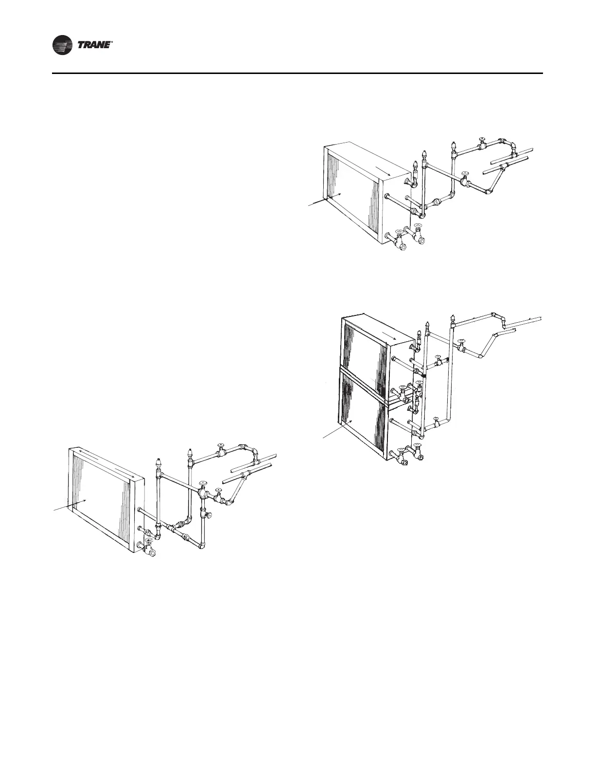
Figure 135. Typical piping for type 5A, 5W two-row, W 3-
to 12-row, WD, D1, and D2 water coils
Figure 136. Typical piping for stacked water coils
AV
AV
AV
GV
Water supply
main
Water
return main
Drain
Pitch down
Airflow
Pitch down
AV
AV
AV
Water
supply main
Water
return main
GV
Drain
Airflow
GV
MV