Routine Maintenance
CLCH-SVX07K-EN 159
6. Remove the collar.
7. Using a socket wrench with an extension, remove the
two nuts that secure the bearing housing to the
bearing support beam.
8. Slide the bearing from the shaft. Note that slight hand
pressure against the wheel rim will lift the weight of
wheel from the inner race of the bearing to assist in its
removal and installation. The use of a bearing puller
may be required.
9. Using a wrench, remove the diameter seal retaining
screws or hub seal retaining screws and remove the
diameter seals or hub seals from the bearing beam.
See Figure 202 for an exploded view of the shaft,
bearings, belt, etc.
.
10. Remove the old belt. Form a small loop of belt and pass
it through the hole in the bearing support beam.
11. Grasp the belt at the wheel hub and pull the entire belt
down.
12. Loop the trailing end of the belt over the shaft.
Figure 202 shows the belt partially through the
opening.
13. Re-install the bearing onto the wheel shaft, being
careful to engage the two locating pins into the holes
in the bearing support beam.
14. Secure the bearing with two self-locking nuts.
15. Install the belt around the wheel and pulley according
to the instructions provided with the belt.
16. Re-install the diameter seals or hub seal and tighten
the retaining screws.
17. Adjust the seals according to the procedure in “Energy
Wheel Seal Adjustment” on page 160.
18. Rotate the wheel in a clockwise direction to confirm
that it rotates freely with slight drag on seals.
19. Re-install the bearing locking collar.
20. Rotate the collar by hand in the direction of wheel
rotation.
21. Lock the collar in position by tapping the drift pin hole
with a hammer and drift.
22. Secure the collar in position by tightening the set
screw.
23. Re-install the bearing access cover.
24. Apply power to the wheel and ensure that the wheel
rotates freely without interference.
For sizes 3 to 8
Bearing removal is not required on slide-out cassettes,
unit sizes 3 to 8. These belts may be replaced by
temporarily dismounting and rotating the pulley side
bearing beam to allow the new belt to be installed on the
wheel rim.
1. Disconnect electrical power to the energy wheel.
2. Remove the access panel.
3. Disconnect all controls wiring.
4. Slide the entire cassette assembly out of the module.
5. Loosen the two set screws on the wheel support beam
bearings, one on each side of wheel.
6. Remove the belt from the pulley and temporarily
position it around the rim.
7. Remove the pulley side wheel support beam with the
bearing.
8. Pull the wheel with the shaft straight out of the motor
side wheel support beam and bearing (see Figure 203).
Do not disassemble the bearings from the beam unless
they require replacement. Handle the wheel with care
to avoid distorting the wheel
.
Figure 202. For belt replacement, loop the trailing end of
the belt over the shaft (shown with diameter
seals removed).
Motor side
Belt (shown in place)
Wheel rim
Wheel
Hub (2)
Taper lock
hub collar (2)
Shaft
Pulley side
Locking collar
Bearing
access plate
Set screw
Drift hole
Locating pin
Pull
Feed
Belt
Adjustable diameter seal
Bearing support beam
Locking nut (2)
Bearing housing
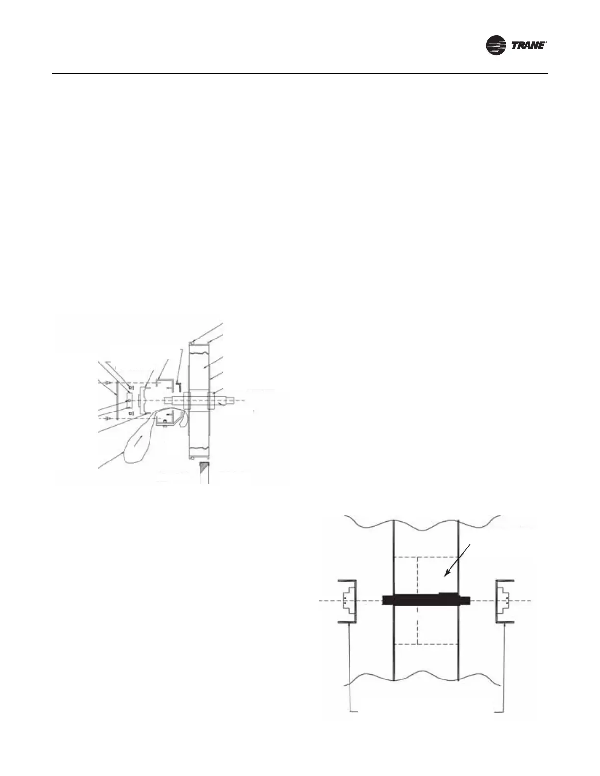
Figure 203. Unit sizes 3 to 8 bearing assembly
Wheel support beam
with bearing
Wheel, hub
and shaft