Installation - Mechanical
CLCH-SVX07K-EN 43
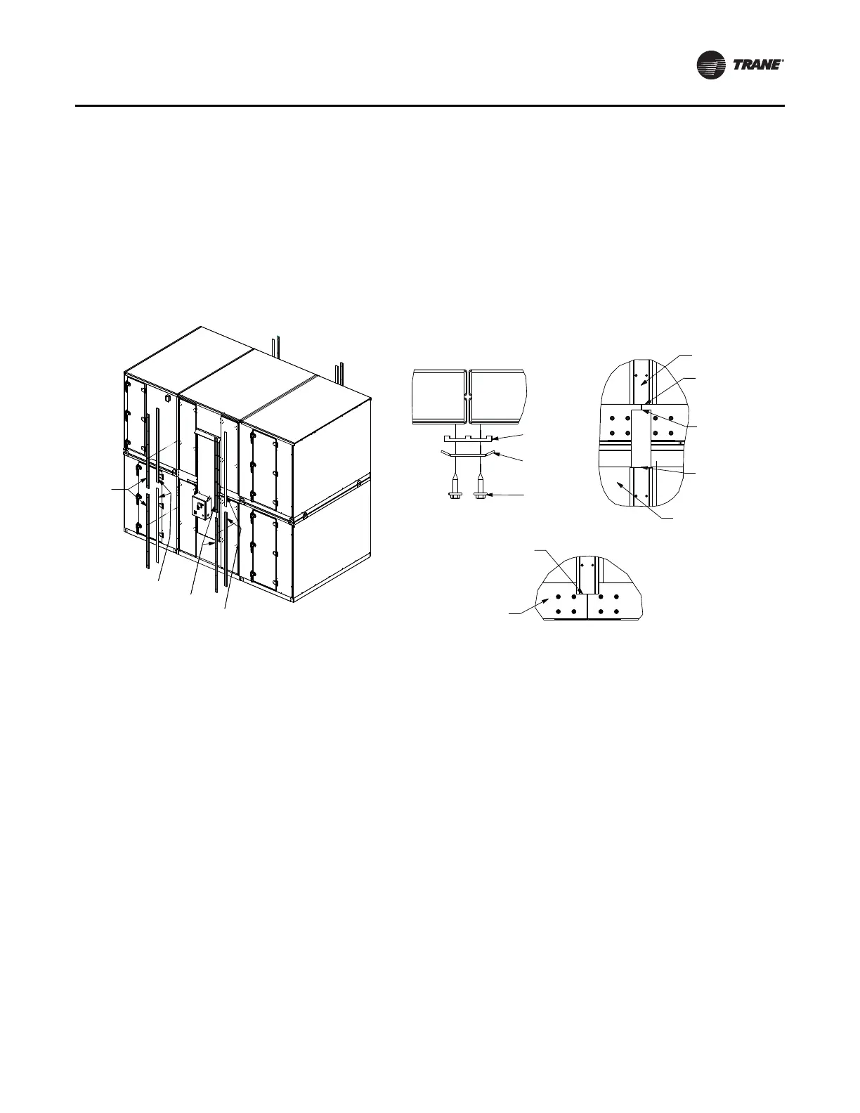
Vertical Seam Cap Installation
1. See Figure 50. Apply ribbed Butyl tape (Item 6) over all
vertical shipping split seams (see Detail A). First level
ribbed Butyl tape (Item 6) starts 1/2 inch below second
level wall panel (see Detail B), and extends down
beyond the bottom of the first level wall panel onto the
base rail at least one inch (see Detail C). Second level
ribbed Butyl tape (Item 6) starts at bottom of wall panel
on second level (see Detail B) and runs up to the top of
the second level wall panel.
2. Secure vertical seam cap (Item 7) over ribbed Butyl
tape (Item 6) with screws (Item 4) (see Detail A). First
level vertical seam cap (Item 7) starts at bottom of hem
on roof panels (see Detail B) and extends down onto
the base rail at least one inch (see Detail D in Figure 55).
Vertical seam cap (Item 7) on second level starts at
bottom of wall panel and extends up (see Detail B).
Second level vertical seam cap (Item 7) may extend
onto the roof panel.
Flashing Installation
For additional information, see “Flashing Installation
Notes,” p. 48.
For hood installations, see “Install Flashing and Hood,”
p. 49.
1. See Figure 51. Apply Butyl tape (Item 8) to
perpendicular-to-airflow flashing (Item 9) and secure
to base rail with screws (Item 4) on front and back of
unit (see Detail A in Figure 55).
2. For energy wheel/CDQ wheel, preassemble end covers
(Item 10 and Item 11) to direction-of-airflow flashing
(Item 12) with screws (Item 4). Apply caulk (Item 14) to
create water tight seal (see Detail B in Figure 53).
3. Apply Butyl tape (Item 8) to direction-of-airflow
flashing (Item 12) and secure to base rails with screws
(Item 4). Start at corners to ensure tight corner seams.
Apply caulk (Item 14) to create water-tight seal (see
Detail A and Detail C in Figure 54).
4. Install seam covers (Item 13) to all flashing seams (see
Detail D in Figure 55).
If second level of unit is shorter than first level, see
“Flashing Installation for Stacked Unit With Second Level
Shorter Than First,” p. 46.
Figure 50. Vertical seam cap installation
(7) Plate:
Vertical
seam cap
(6) Tape:
Ribbed Butyl
(7) Plate:
Vertical
seam cap
(4) Screw:
10-16 x 0.750
self driller
(6) Tape:
Ribbed Butyl
(7) Plate: Vertical
seam cap
(6) Tape:
Ribbed Butyl
Shipping split seams
Detail B
Ribbed Butyl tape and
seam cap flush with
bottom of wall panel
First level ribbed
Butyl tape 1/2 inch
below second level
wall panel
First level seam cap
starts at bottom of
hem on roof panel
First level
Ribbed Butyl tape and seam
cap extend beyond the bottom
of wall panel onto base rail at
least one inch
First level
Second level
Detail C
Detail A