Start-Up
CLCH-SVX07K-EN 129
.
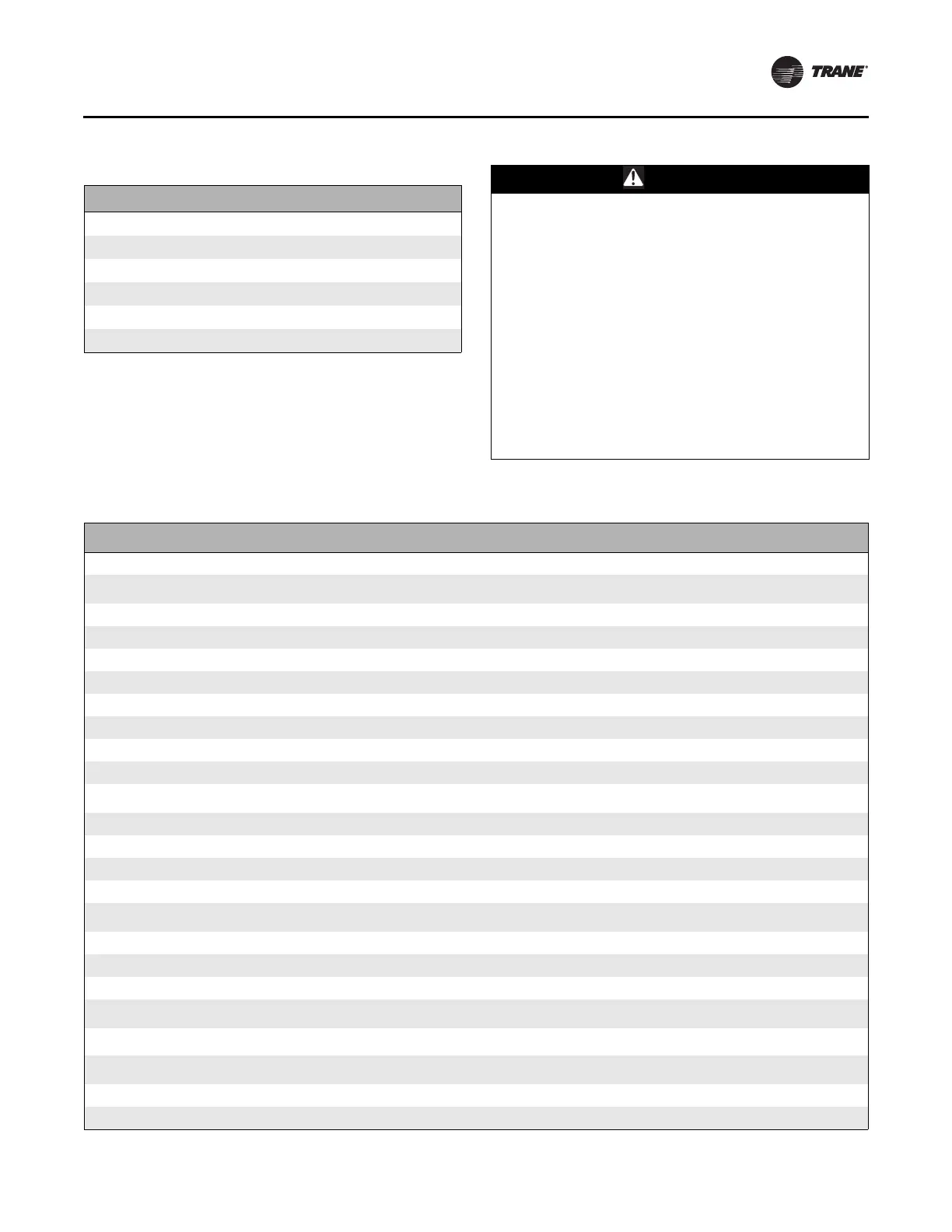
Table 38. Trane TR150 Switching Frequency
Horsepower Voltage Max KHz Trane Setting
0.5 - 15 208/230 16 16
20-60 208/230 12 12
0.5 - 30 460 16 16
40 - 125 460 12 12
0.5 - 10 575 12 12
15 - 125 575 8 8
WARNING
Hazardous Voltage w/Capacitors!
Failure to disconnect power and discharge capacitors
before servicing could result in death or serious injury.
Disconnect all electric power, including remote
disconnects and discharge all motor start/run
capacitors before servicing. Follow proper lockout/
tagout procedures to ensure the power cannot be
inadvertently energized. For variable frequency drives
or other energy storing components provided by Trane
or others, refer to the appropriate manufacturer’s
literature for allowable waiting periods for discharge of
capacitors. Verify with an appropriate voltmeter that all
capacitors have discharged.
For additional information regarding the safe discharge
of capacitors, see PROD-SVB06*-EN
Table 39. Trane TR150 VFD Programming Parameters
Parameter #
TR150 Description Factory Default Trane Setting
0-03 Region International North American
1-03 Torque Characteristics Auto Energy Optim. VT
Auto Energy Optim. VT [3]for Belt-Drive Fans
Variable Torque [1]for Direct-Drive Fans
1-20 Motor Power Depends on unit Set Based on Motor Nameplate
1-22 Motor Voltage Depends on unit Set Based on Motor Nameplate
1-24 Motor Current Depends on unit Set Based on Motor Nameplate
1-25 Rated Motor Speed Depends on unit Set Based on Motor Nameplate
1-71 Start Delay 0.0 Sec 2 Sec
1-73 Flying Start Disabled Enable
1-90 Motor Thermal Protection ETR Trip 1 [4] ETR Trip 1 [4]
3-02 Minimum Reference Application dependant 0 Hz
3-03 Maximum Reference 60Hz
60 or the Value of Maximum Inverter
Frequency (Hz) on nameplate if fan is direct drive.
3-15 Terminal 53 Analog Input Analog Input 53 Analog Input 53
3-41 Ramp-up Time Application dependant 30 Sec
3-42 Ramp-down Time Application dependant 30 Sec
4-12 Output Freq Low Limit Application dependant 20 Hz
4-14 Output Freq High Limit
60 or the Value of Maximum Inverter
Frequency (Hz) on nameplate if fan is direct drive.
60 or the Value of Maximum Inverter
Frequency (Hz) on nameplate if fan is direct drive.
4-18 Current Limit Application dependant 110%
4-19 Max Output Frequency Application dependant 65 Hz or 120 Hz for Direct Drive Fan
5-12 Terminal 27 Digital Input No Operation Coast Inverse
5-40 Function Relay No Operation
Relay 1 Active No Alarm [160]
Relay 2 Active Motor Running [5]
6-14
Terminal 53 Low Ref
Feedback
0.0 Hz 20 Hz
6-15
Terminal 53 High Ref
Feedback
Application dependant
60 or the Value of Maximum Inverter
Frequency (Hz) on Nameplate if fan is direct drive.
14-01 Switching Frequency 5.0 kHz Set to Max for HP (see Table 38)
14-20 Reset Mode Manual Reset Automatic Reset x 5