Start-Up
132 CLCH-SVX07K-EN
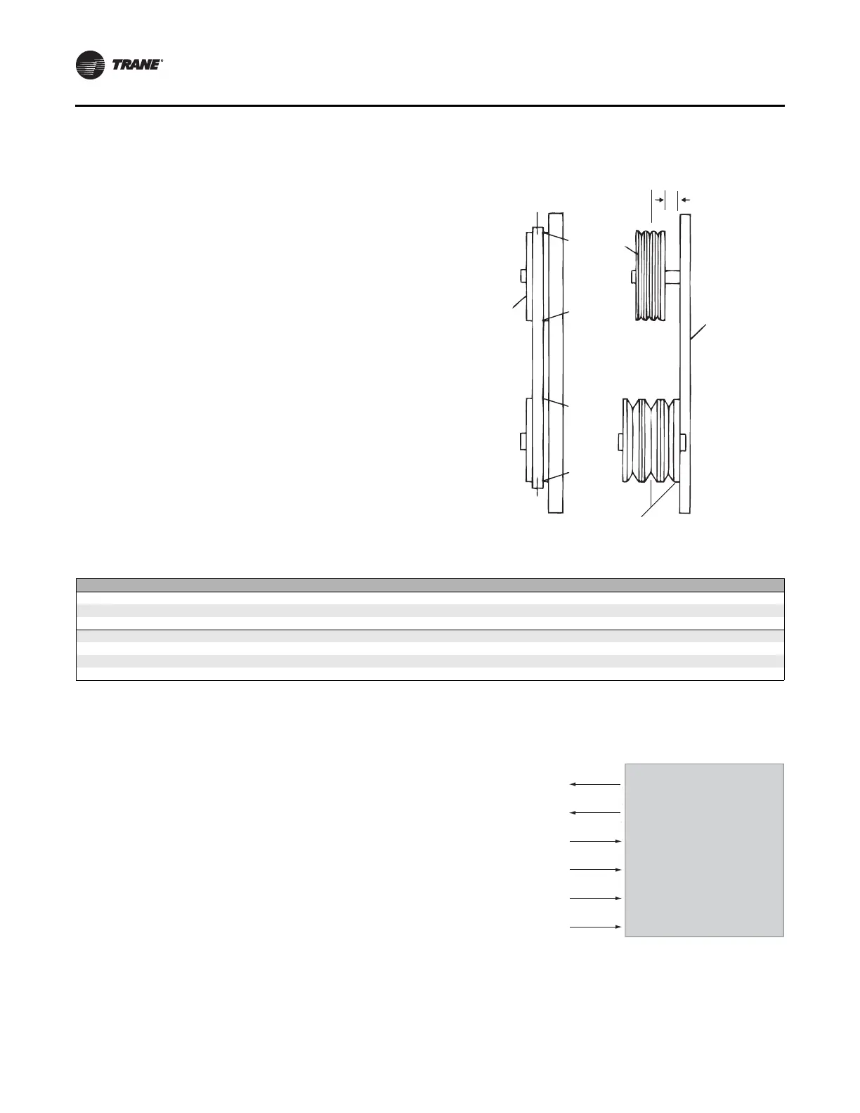
Align Fan and Motor Sheaves
Align the fan and motor sheaves using a straightedge. The
straightedge must be long enough to span the distance
between the outside edges of the sheaves. When the
sheaves are aligned, the straightedge will touch both
sheaves at points A through D (see Figure 165) to confirm
the shaft is parallel. For uneven width sheaves, place a
string in the center groove of both sheaves and pull tight.
Adjust the sheaves and tighten the sheave set screws to
the proper torque given in Table 41.
Check Multiple Belts
Tighten the belts slightly and rotate the drive several
times.
On multiple belt drives, ensure the force of deflection is
approximately the same on each belt by pushing each belt
in an equal distance at a point halfway from each sheave
(see Figure 165). If this force is not the same for each belt,
the motor and fan shaft are not parallel. Realign as
required. After realignment, tighten the belts again to the
standard belt tensioning specifications. If the force is still
not the same for all belts, the belts or sheaves are worn
and must be replaced.
Airflow Measuring Systems
Traq™ Dampers
Traq dampers are low-leak dampers that modulate and
measure airflow. Each Traq damper section is supplied
with a factory-mounted ventilation control module (VCM)
on the interior of the mixing box section. The VCM has an
input terminal for power and an output terminal for air
velocity (see Figure 166). A direct-digital controller
controls the factory-mounted and wired actuators.
Figure 165. Proper drive alignment
D
Fixed
Sheave
C
B
A
Adjustable
Sheave
Straight
Edge
Lines must
be parallel
Center line
must coincide
Fixed
Sheave
Table 41. Set screw torque settings (inches)
Screw Size Hex Key Square Head Hex Head Torque (in.-lb.) Torque (ft.-lb.)
1/4 1/8 3/8 7/16 66-90 5.5-7.5
5/16 5/32 1/2 1/2 126-164 10.5-13.7
3/8 3/16 9/16 9/16 228-300 19.0-25.0
7/15 7/32 5/8 5/8 348-450 29.0-37.5
1/2 1/4 3/4 3/4 504-650 42.0-54.2
5/8 5/16 15/16 15/16 1290-1390 107.0-116.0
#10 3/32 - - 28-40 2.3-3.3
Figure 166. Traq damper terminal connections
Ventilation Control Module
Velocity (2-10 Vdc)
GND
24 Vac
GND
J4 (Red)
J4 (White)
J2 (Black)
J2 (Green)
J5 (Yellow)
J5 (White)
Thermistor