Installation - Mechanical
CLCH-SVX07K-EN 41
Pipe Cabinet to be Installed at Shipping Split
Joint
1. Remove threaded rod and unit lug that is outside of
pipe cabinet.
2. Using three screws from unit lug, install black lug
replacement plate in place of unit lug. See Figure 47
Detail C.
3. Lift pipe cabinet into place on roof curb.
4. Slide pipe cabinet into place.
5. Put threaded rod through pipe cabinet lifting lug into
weld nut inside baserail to pull the pipe cabinet tight
against the unit. See Figure 47 Detail D.
Pipe Cabinet to be Attached to Unit Base
Bracket
1. Lift pipe cabinet into place on roof curb.
2. Slide pipe cabinet into place.
3. Put threaded rod through pipe cabinet lifting lug into
welded unit base rail bracket to pull the pipe cabinet
tight against the unit. See Figure 47 Detail E.
Pipe Cabinet to be installed at a Factory Joint
1. Lift pipe cabinet into place on roof curb.
2. Slide pipe cabinet into place.
3. Put threaded rod through pipe cabinet lifting lug into
weld nut inside base rail to pull the pipe cabinet tight
against the unit. See Figure 47 Detail F.
Completing Pipe Cabinet Installation
1. Install inside corner cap. See Figure 47.
2. Install 3/8-in. white Butyl tape to unit wall where pipe
cabinet roof connects.
3. Lift pipe cabinet roof into place and attach to unit wall
with screws. See Figure 47.
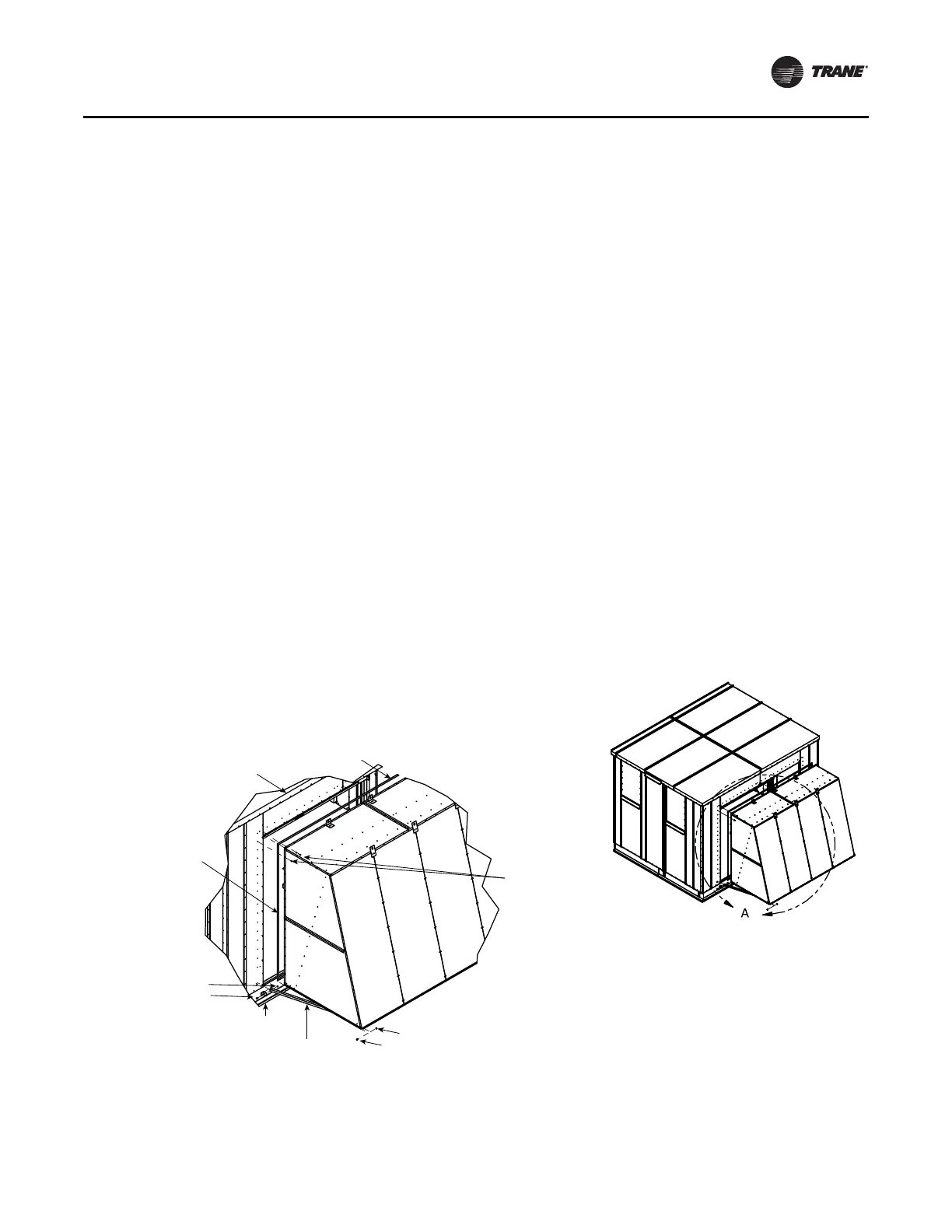
Hood Installation
1. Per the unit drawing determine mounting location of
the unit weather hoods.
2. Using the factory provided screws mount the weather
hoods to the unit.
3. On larger units, weather hoods may be large enough to
require angled down supports. In those cases, the
angles are shipped attached to the hood but will need
to be connected to the air handler by the installing
contractor. See Figure 48.
Note: It is required that the hoods be sealed to the unit
using factory-provided butyl/caulk tape.
Figure 48. Hood installation
AHU outdoor roof
Butyl caulk tape
1.00 W x .125T
Hood
Nut-Hex .31-18
Detail A
Screw self-driller
10-16 x .750
or
1/4-in. x .750
Butyl caulk tape
1.00 W x .125T
Nut-Hex .31-18
Bolt .313-18 x .750 Hex
Bracket Support
Angle Hood Support
(when required)
Bolt .313-18 x .750 Hex