Installation - Electrical
CLCH-SVX07K-EN 117
• Install outside-air sensor and space sensor, if ordered.
• Connect control valves, if ordered, to the valve jack
provided as part of the unit wiring harness. The valve
jack is typically located at the air-leaving side of the coil
connection inside the casing panel. For valve junction
box mounting and wiring detail, see Figure 152.
Quick Connects
The actuators, factory-mounted or field-supplied, are
separately wired and controlled by a direct-digital
controller or other building logic. Figure 153 illustrates the
typical quick connect scheme.
Note: With units that require splits to be assembled that
have high voltage quick connects, use wire ties to
bind the quick connections together to avoid poor
connections or intermittent connection from
vibrations.
If the unit does not include a factory-mounted starter,
wiring to the unit fan motor must be provided by the
installer and must comply with all national and local
electrical codes. The installer must also furnish a service
disconnect switch in compliance with national and local
electrical codes.
Fan motors require motor overload protective devices that
are rated or selected in compliance with the National
Electric Code (NEC) or Canadian Electric Code. Specific
unit and motor connection diagrams are provided on the
starter/VFD if Trane-provided, or refer to the motor
nameplate.
If wiring directly to the motor, a flexible connection at the
motor to permit fan belt adjustment should be provided.
Fractional horsepower motors may be factory connected
to a terminal box on the unit. If this construction is
provided, the installer should complete field wiring to this
connection box. For a typical wiring schematic, see
Figure 155 thru Figure 160.
Note: Properly seal all penetrations in unit casing. Failure
to seal penetrations from inner panel to outer panel
could result in unconditioned air entering the unit.
CDQ™ Desiccant Wheel Cassette/
Motor
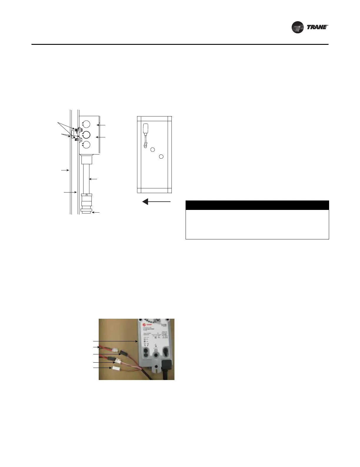
Figure 152. Junction box for valve wiring
Figure 153. Typical quick connects with wiring.
#10
self-drilling
screws (2)
2 x 4
junction box
Cover
Conduit
assembly
Valve
connection
End panel
Double-
wall panel
Bushing
(2 required
for units with
double-wall)
Airflow
Wiring:
Red/black - power (hot)
White/pink - control signal (in)
Orange/gray - feedback (out)
Actuator
Wiring harness
Power 24 Vac
Control signal (2-10 Vdc)
Feedback signal
NOTICE
Wheel Motor Failure!
Failure to follow instructions below could result in
failure of the wheel motor. Do not use a variable
frequency drive (VFD) to control the wheel speed.