6 AU-OPR-AureFloFT-EN,
Rev H
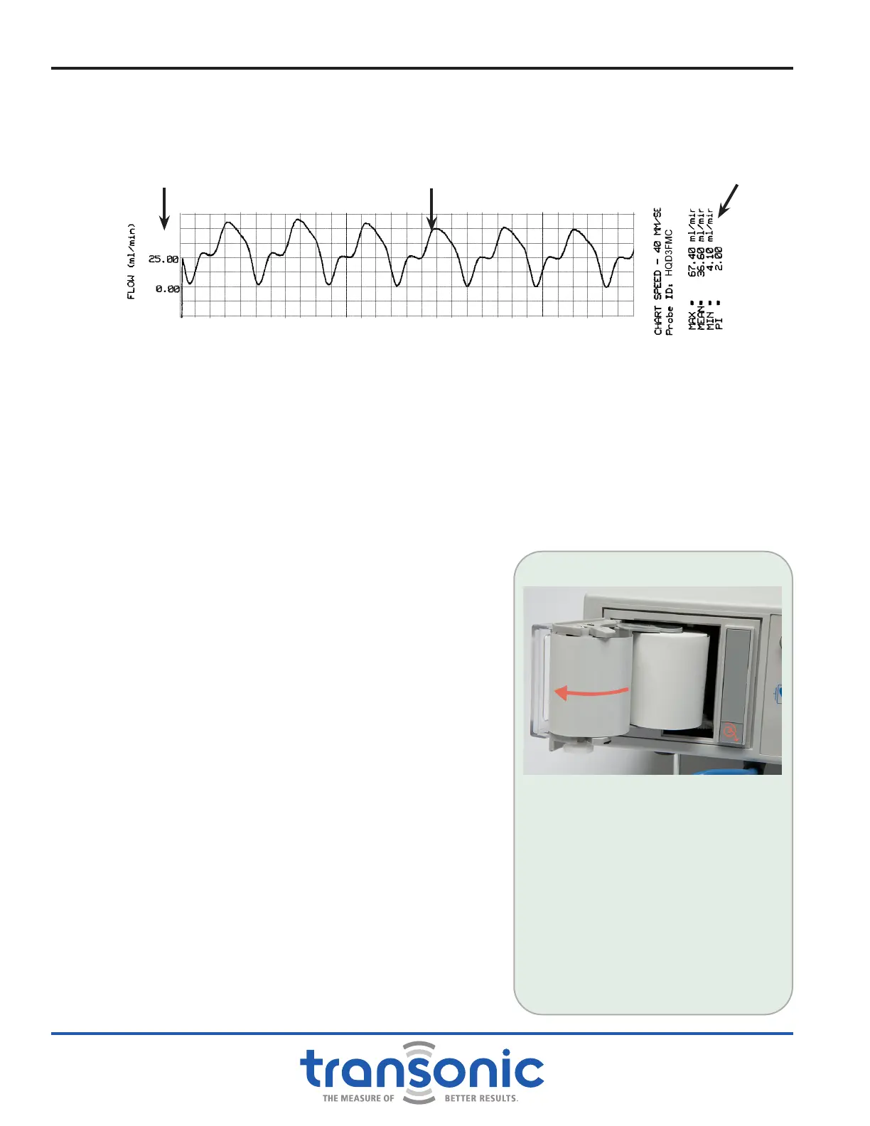
3. CHART RECORDER (Not provided on Models HT310-FT, HT320-FT, HT350 & HT360)
The chart recorder is used to document ow measurements, including phasic ow patterns (Fig. 2.4).
It automatically scales for the full range of ow measurements.
The chart recorder has 3 settings, selected by the rear panel Chart Recorder slide switch:
a) RUN/STOP prints continuously at 20 mm/sec; push the [Print] button to start/stop printing.
b) SLOW prints 8 seconds of ow data at 20 mm/sec: SELECT THIS MODE FOR ROUTINE OPERATION
c) FAST prints 4 seconds of ow data at 40 mm/sec.
TESTING THE CHART RECORDER: Push [Print] button. When engaged, the chart recorder prints a
header and then pauses momentarily while the paper is automatically scaled to actual ow conditions.
The chart recorder will then print a strip of ow data in real time. There is another brief pause toward
the end of the print run while ow statistics are calculated.
The print cycle can be interrupted at any time by pushing
the [Print] button a second time. Once the chart recorder
has stopped, pushing the [Print] button a third time will
initiate a new print cycle. In “RUN/STOP” Mode the chart
recorder will print continuously until the user pushes the
[Print] button a second time.
The printout is scaled to the ow conditions 8 seconds prior
to printing. Scaling cannot be modied during a print run.
Therefore, if ow increases dramatically while printing, the
measurements will go off scale. Wait until the mean values
have stabilized before attempting to print again.
CHART RECORDER END OF PROBE LIFE MESSAGE:
As the Flowprobe approaches its use limit, the following
message will be printed on the strip chart recorder:
Attention: Probe serial # xxxxxxxxxx has reached the end
of its calibration period. Please contact Transonic Systems
Customer Service @ 1-800-353-3569 to order a replacement
Flow-QC
®
Probe.
NOTE: Date and time on the chart recorder printout
come preset from the factory. Call Customer Service for
instructions.
LOADING THE THERMAL PAPER
1) To open door, press the bottom of
the gray bar on the recorder.
2) Remove empty paper spool.
3) Place a new spool of paper on the
paper holder so that the paper exits
the spool from the left-hand side.
4) Thread the paper through the
front panel paper deector of the
recorder.
NOTE: Installing paper with incorrect
side out will prevent proper printing.
Functions & Controls
Fig. 2.4: Chart Recorder print out
Waveform
Flow Data
Flow Scale