22 AU-OPR-AureFloFT-EN,
Rev H
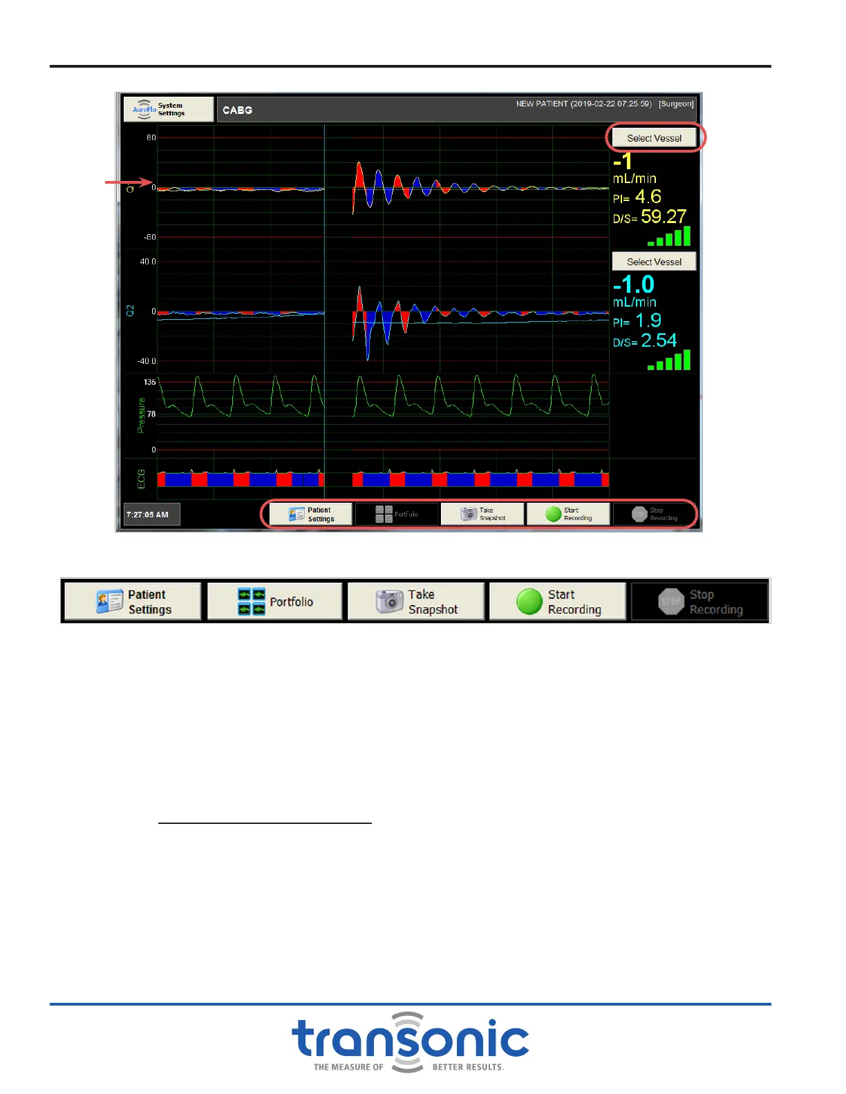
Fig. 6.2: FlowTrace
®
screen in Realtime mode. A single Flowprobe is connected as seen by the Q1 channel on the left side. Ultrasonic
signal coupling is good as indicated by the ve green bars. Pressure and ECG signals are connected.
Fig. 6.3: Menu buttons found at the bottom of Realtime mode
AureFlo
®
Operation
A. Realtime Mode: Realtime Display of Flow Waveform & Data
A typical realtime display will include (Fig. 6.2):
1) Q1: Flow Waveform with diastolic lling in blue and systolic lling in red
2) Mean Flow over eight seconds in mL/min. The mean ow line is shown in green on the waveform.
3) Pulsatility Index (PI):
PI =
Maximum Flow-Minimum Flow
Mean Flow
4) Diastolic Fraction (DF) is interchangeable with D/S Flow Ratio (see page 17). For further description of
the D/S Ratio and DF, see Appendix C: ECG Signal, D/S Ratio & DF, page 39.
5) Signal Strength displayed as colored bars.
6) Pressure signal if connected.
7) ECG signal at the bottom of the screen if connected; colorized to indicate systole and diastole.
Mean
ow line