14 AU-OPR-AureFloFT-EN,
Rev H
D. Testing The Flowprobes
NOTE: Flow-QC
®
keys are not required to test signal quality. Single use Probes should only be tested shortly
before use as the signal test will begin the measurement period.
1) Immerse the Flowprobe in a container lled with sterile saline to establish ultrasonic coupling.
2) Dislodge any air bubbles from the Flowprobe’s surfaces. Gently move the Flowprobe back and forth in
the saline to remove all air bubbles.
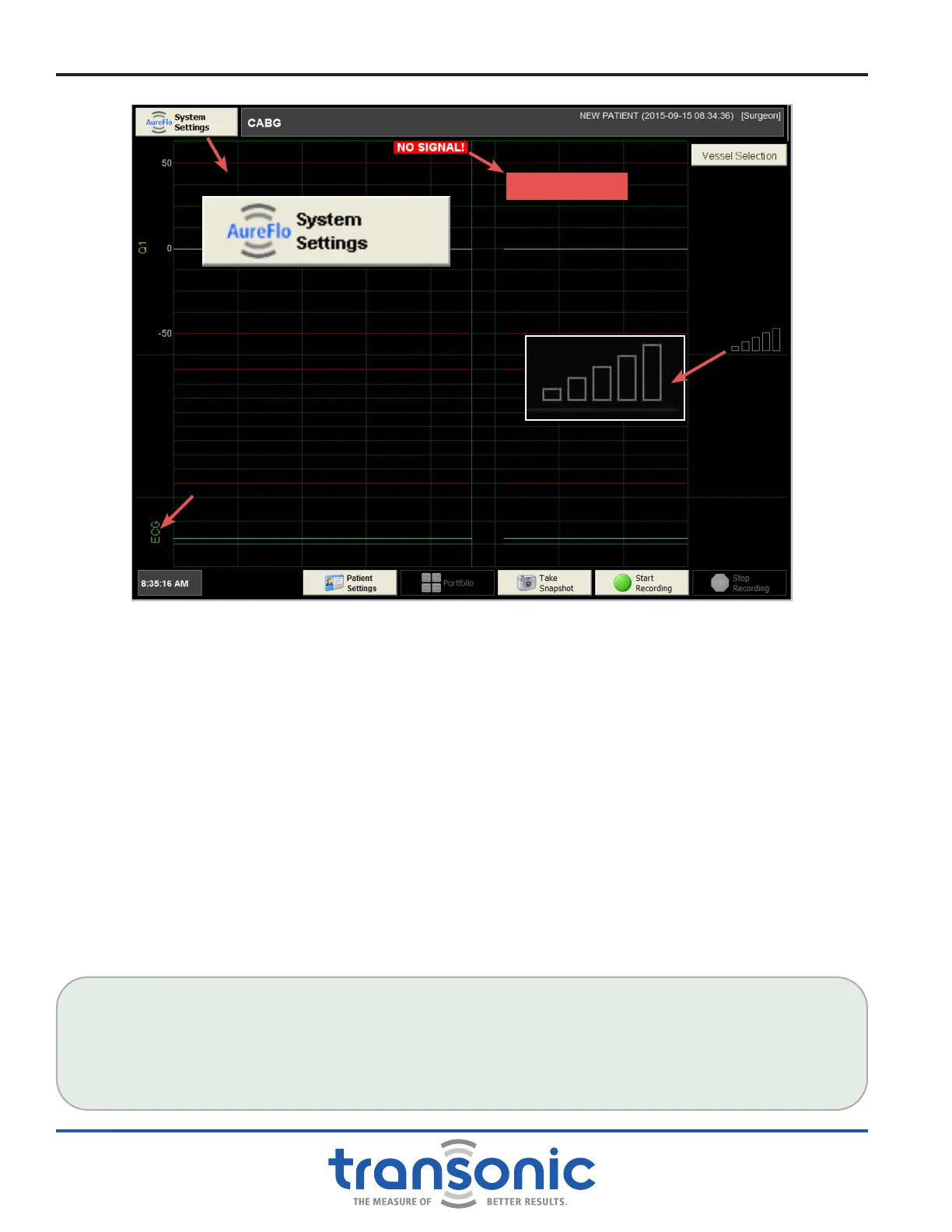
3) Observe the Signal Indicator Display on Realtime mode (Fig. 4.4). The bars will change from black to red
to yellow to green as the strength of the signal increases and acoustic transmission is established (Fig.
4.5, page 15).
4) When a Flowprobe is connected and there is adequate ultrasonic transmission, ow can be measured.
This is indicated by a waveform on the scrolling bar of the touch-panel display.
Functional Tests
FLOWPROBE/FLOWSENSOR QUALITY TEST
Three yellow bars indicate an adequate signal strength for ow measurements with Flowprobes/
Flowsensors. However, ultrasound signal attenuation will be higher on blood vessels during surgery.
Therefore, the Flowprobe/Flowsensor quality acceptance level during saline testing should be at least four
green bars.
Fig. 4.4: FlowTrace
®
screen in Realtime mode. The “NO SIGNAL” message at top of the screen and signal
indicator lights on the touch-panel display’s right side indicate that the Flowprobe is not receiving
ultrasonic transmission.
NO SIGNAL!
ECG Signal