28 AU-OPR-AureFloFT-EN,
Rev H
A. Intraoperative Measurements with Perivascular Flowprobes
FLOWPROBE SETUP
The Flowprobe has been factory calibrated to
meet Transonic
®
Flowprobe Specications when
applied to a living vessel (see package insert
sheet). No on-site calibration is needed. The
functional test described on page 14 may be
repeated on the sterile eld.
CLEANING & STERILIZATION
Perivascular Flowprobes must be sterilized before
each surgical use. See AU-IFU-ProbeSterilization
“Cleaning & Sterilization of Transonic
®
Flowprobes” for instructions.
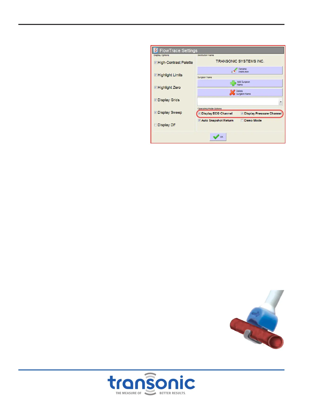
CHECK ECG OR PRESSURE SIGNAL
If using ECG or Pressure, check that the signal
is reading correctly, and that ECG, and if used,
Pressure, is checked on the FlowTrace
®
Settings
screen (Fig. 7.1).
PREPARE VESSEL
The surgeon will isolate a section of the vessel in which ow will be measured. Although it is not necessary
to fully skeletonize the vessel, special care should be taken to remove all fatty tissue which may be within
the Probe’s owsensing window.
FLOWPROBE SELECTION
Select a Flowprobe size for a non-constrictive (loose) t on the vessel to be measured. The vessel diameter
should be between 75% and 100% of the width of the Flowprobe’s owsensing window.
ULTRASONIC COUPLANT
Ultrasonic couplant is needed to establish ultrasonic contact between the Flowprobe and the vessel. Sterile
ultrasound gel or sterile saline may be used at the surgeon’s discretion. Ultrasonic couplant is best applied
into the Probe’s ultrasonic sensing window just before the Probe is applied to the vessel. When ultrasonic
contact is established, Realtime mode of the AureFlo
®
touch-panel display will show a waveform scrolling
across the window.
APPLY FLOWPROBE
Perivascular Probes with reectors: Apply the Flowprobe so that the vessel lies perpendicular to the
longitudinal axis of the Flowprobe within the owsensing window formed by the Probe’s body and the
attached reector (Fig. 7.2). AU-Series Cardiac Output Probes: the vessel is inserted
into the opening of the C-shaped Flowprobe. Flowprobes may be oriented in
either direction relative to ow. Avoid placing the Probe over metal clips, sutures,
and fatty tissue.
FLOWSOUND
®
After setting up the AureFlo
®
System and testing the Flowprobes with FlowTrace
®
,
turn on FlowSound
®
on the front panel of the HT300 Series Compatible Flowmeter.
Adjust FlowSound
®
volume on back of the Flowmeter. Listening to FlowSound
®
while observing the heart’s contractions gives an instantaneous assessment of ow
conditions.
Fig. 7.1: ECG and Pressure display checked on FlowTrace
®
Settings
screen
Fig. 7.2: Flowprobe alignment
perpendicular to vessel
VII. Directions For Flowprobe Use