AU-OPR-AureFloFT-EN,
Rev H
13
Functional Tests
B. Connecting a Printer
If you have purchased a printer from Transonic Systems
Inc.
®
, your printer’s cord is already connected to the
AureFlo
®
Cart’s integrated medically isolated power
supply and the printer driver has been installed on the
AureFlo
®
Panel PC. The printer will always need to be
turned “ON” via the [On/Off] button on the printer if
the power to the AureFlo
®
Cart has been turned “OFF”.
IMPORTANT: ONLY USE A PRINTER THAT IS POWERED FROM THE
SUPPLIED, MEDICALLY ISOLATED 18 VDC CONNECTOR.
For a printer not purchased from Transonic
®
:
1) Verify the connection of the supplied USB cable
to the appropriate port on the rear of the printer.
Verify the connection of the opposite end of the USB
cable to an available port on the Panel PC.
2) Connect the loose end of the printer’s power cord
& adaptor cable to the power port on the rear of
the printer. Power “ON” the printer via the printer’s
[On/Off] button. Note: Depending on the printer a
different adaptor cable may be required.
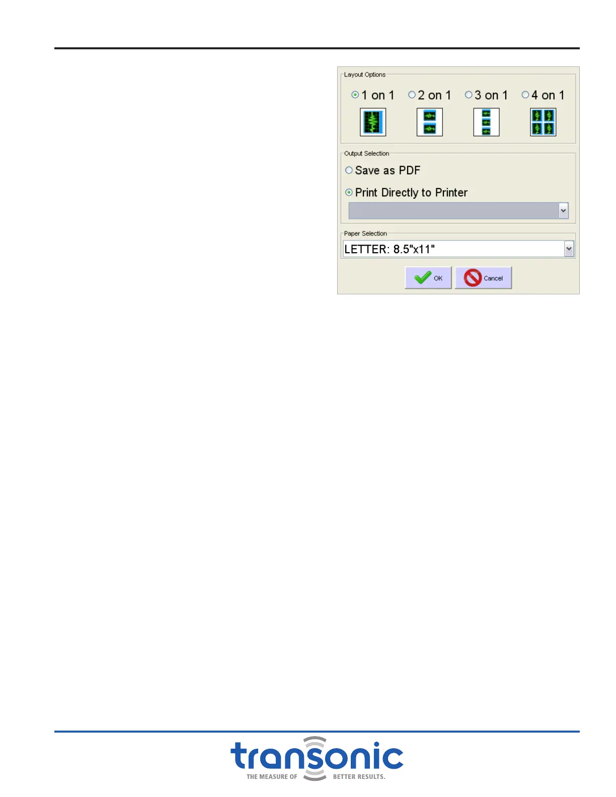
Printing options are controlled from the dialog box that opens after selecting [Print] (Fig. 4.3).
C. Testing The AureFlo
®
System
The following tests acquaint the user with operation of the AureFlo
®
System:
1) Turn on AureFlo
®
System per instructions above. If the system is on but FlowTrace
®
is not open, double
click the FlowTrace
®
icon on the desktop of the Monitor. During FlowTrace
®
startup the AureFlo
®
Monitor will display a start-up message. The Realtime screen will be displayed with the message “Plug in
Flowprobe.” This indicates that there is still no Flowprobe/Flowsensor connected to the Flowmeter.
2) From the [System Settings] menu, use the [FlowTrace
®
Settings] dialog on the AureFlo
®
Monitor
to enter the institutions’s name for display on printouts only. Enter all Surgeon's names for inclusion in
patient information. The default surgery is the last surgery selected and all FlowTrace
®
Settings default
to last selected (Fig. 7.1, page 28). If nothing has previously been selected the default surgery is CABG
and all FlowTrace
®
settings are selected as active.
3) Use the [Patient Settings] menu to update patient name and information. Update surgery type if
necessary.
4) Use the self-aligning push-lock connector to connect a Flowprobe or Flowsensor to the Probe extension
cable at the front of the Flowmeter. Make sure that the connector is fully pushed in. The AureFlo
®
Monitor’s display will show “NO SIGNAL” at the top center of the new screen (Fig. 4.4, page 14).
The ve black bars on the right-hand side of Fig. 4.4 indicates that there is no ultrasonic transmission
reaching the Flowprobe because there is no acoustic coupling. See Fig. 4.5 on page 15 for signal
indicator bar strength explanation.
Fig. 4.3: Print options dialog box. Printer drop-down menu is
only available if multiple printers are installed on the
AureFlo
®
system.