12 AU-OPR-AureFloFT-EN,
Rev H
IV. Functional Tests
A. Setting Up The AureFlo
®
System
When you receive your AureFlo
®
System, all power cords will be attached to
the AureFlo
®
Cart’s medically isolated power source. Before turning on the
AureFlo
®
System these power cords must be connected to the touch-panel
PC, an HT300 Series Compatible Flowmeter and the optional printer. Use the
following steps to set up your AureFlo
®
System for more detailed instructions
see (Appendix A: Initial AureFlo
®
Setup, page 35).
1) Prior to making any connections on your AureFlo
®
System, make sure that
the line cord is disconnected from the AureFlo
®
Cart and the system is powered
“OFF”.
a) Position and attach the AureFlo
®
touch-panel PC to the AureFlo
®
Cart.
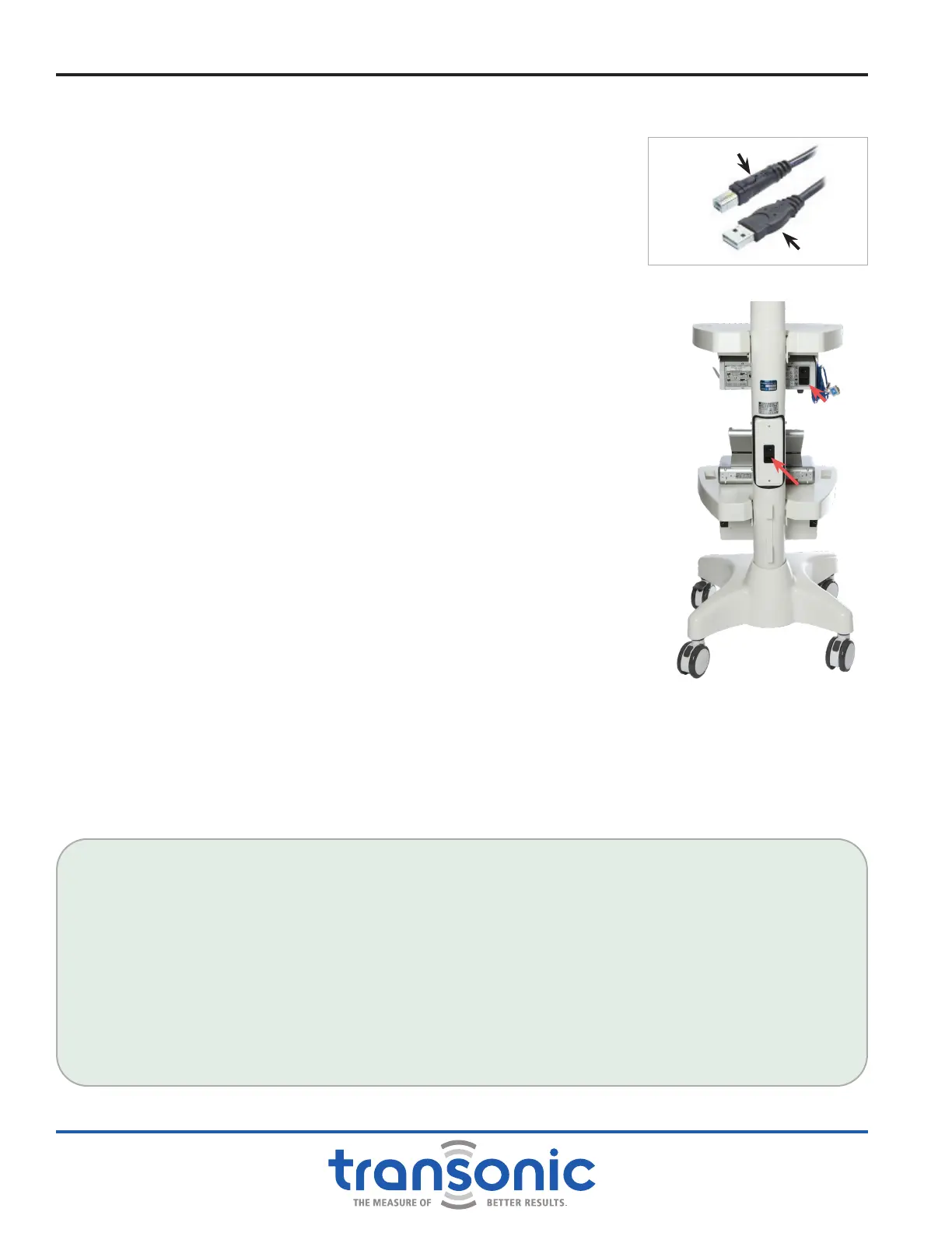
Connect one end of the USB cable to a Flowmeter (Fig. 4.1). Then
connect the opposite end to any open USB port on the bottom of the
AureFlo
®
touch-panel PC.
b) AureFlo
®
Cart’s Power Cords:
i) Connect one power cord from the AureFlo
®
Cart to the Universal
Power Supply port of the Flowmeter. With the AureFlo
®
Cart’s line
cord still disconnected, turn the Flowmeter’s power switch to “ON”
and leave it in the “ON” position.
ii) Connect the other power cord from the AureFlo
®
Cart to the
Universal Power Supply port of the AureFlo
®
touch panel PC which is
wired to turn on automatically.
c) Line Cord: connect one end of the line cord to the Universal Power
Supply port on the AureFlo
®
Cart. Connect the line cord to an electrically
grounded power receptacle.
2) Now turn on the AureFlo
®
System via the [Power On/Off] switch on the back
of the AureFlo
®
cart (Fig. 4.2).
3) FlowTrace
®
will start automatically and display on the AureFlo
®
Panel PC.
A FlowTrace
®
dialog displaying “PLUG IN A FLOWPROBE” will appear.
FlowTrace
®
is now ready to use.
IMPORTANT! EXIT FLOWTRACE
®
SOFTWARE AND POWER DOWN THE MONITOR BEFORE TURNING OFF POWER ON THE
CART. FAILURE TO PROPERLY POWER DOWN THE SYSTEM MAY CAUSE SYSTEM ERROR. FOLLOW THE DIRECTIONS IN "AFTER
MEASUREMENTS ARE COMPLETED" ON PAGE 30 FOR PROPER SHUTDOWN METHOD.
ECG / PRESSURE SIGNAL: IF PERFORMING SURGERY IN WHICH AN ECG AND/OR PRESSURE SIGNAL IS
DESIRED, CONNECT THE ECG /PRESSURE SIGNAL FOR USE WITH THE AUREFLO
®
SYSTEM AS FOLLOWS:
● Identify an appropriate ECG / Pressure source on the anesthesia patient monitor (with assistance from
perfusion or Biomedical Engineering, if necessary). This will be the same port as that used for the Intra-
Aortic Balloon Pump. The maximum voltage input is -5V to +5 V.
● Connect the anesthesia monitor to the AureFlo meter with the supplied cable, using the ECG or Pressure
port. Make sure both ends are connected to the same output, either 'ECG' or 'Pressure'.
● If the connection is not a 1/4" phono plug, a different cable will have to be specied and ordered
through Transonic.
● Turn on the ECG / Pressure source.
Connect to Flowmeter
Connect to Monitor
Fig. 4.1: USB Cable
Fig. 4.2: AureFlo
®
Cart rear pole
view with [On/Off]
switch
Flowmeter
On/Off
Cart On/Off