AU-OPR-AureFloFT-EN,
Rev H
35
A. AureFlo
®
Assembly
This section describes AureFlo
®
assembly and the launch of FlowTrace
®
software.
1) Turn off Power Module power switch on Pole by depressing circle.
2) Secure the AureFlo
®
Monitor to the AureFlo
®
Cart
a) Install 2-M4 screws in the top two holes on the back of the AureFlo
®
Monitor. Do not tighten. Allow
1/8 to 1/4 inch protrusion.
b) Attach the AureFlo
®
Monitor to the AureFlo
®
Cart by sliding the two screws on the AureFlo
®
Monitor into the slots on the VESA mount.
c) Install 2-M4 screws in the bottom two holes of the VESA mount and tighten.
d) Tighten the top two screws to secure the AureFlo
®
Monitor to the AureFlo
®
Cart.
e) Connect the AC power cord to the AureFlo
®
Monitor input power connection.
f) Connect the USB cable to any USB port on the AureFlo
®
Monitor.
3) Install the HT300 Series Compatible Flowmeter to the AureFlo
®
Cart
a) Slide the Flowmeter into the mounting bracket under the top shelf. This does not require the
removal of the Flowmeter feet.
b) Secure the Flowmeter to the AureFlo
®
Cart using two 10-32 thumb screws.
c) Connect the AC power cord to the AC input on the Flowmeter.
d) Connect the USB cable to the USB output jack on the Flowmeter.
e) Turn the Flowmeter’s power switch to the “ON” position. (Note that the Flowmeter will not power
up until there is power to the AureFlo
®
Cart).
f) Connect the power cord to the AureFlo
®
Cart via the Universal Power Supply port. Connect the
opposite end of the line cord to an electrically-grounded power receptacle.
g) Turn on the pole switch to the “ON” position. Note that the Monitor will automatically boot, and
the Flowmeter will turn on.
4) Add Printer (optional) to the AureFlo
®
Cart
a) Place printer on the bottom shelf of AureFlo
®
Cart.
b) Route the USB cable through the pole’s top hole/bottom hole.
c) Connect USB cable to USB output jack on back of printer.
d) Connect USB cable to any free/open USB port on the AureFlo
®
Monitor.
e) Connect printer to power cable using the included adapter and adapter cable.
f) Connect printer via adaptor cable to printer power cord from the AureFlo
®
Cart.
B. Installing FlowTrace
®
Software Initially
(NON-U.S. CUSTOMERS WHO ORDERED THE MONITOR
SEPARATELY OR THOSE RECEIVING A REPLACEMENT ONLY)
1) Follow the assembly directions above prior to
installing the FlowTrace
®
software making sure that
the Flowmeter and Monitor are connected and
powered on.
2) Insert FlowTrace
®
software installation CD.
FlowTrace
®
installation will auto-start.
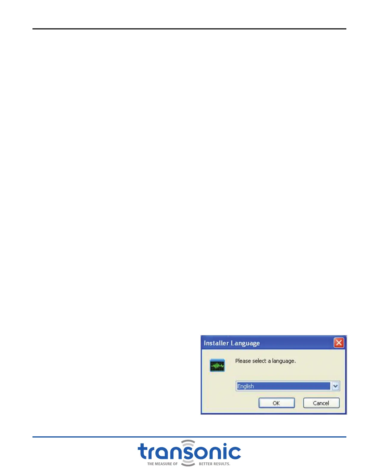
3) Windows will prompt you to select a language then
select [OK] (Fig. A.1),.
Appendix A: Initial AureFlo
®
Setup
Fig. A.1: Select language screen