19 Cables and Connectors
120 Trimble R6/R7 GPS and Trimble R8 GNSS Receivers User Guide
Trimble R6 GPS and R8 GNSS Receiver Operation
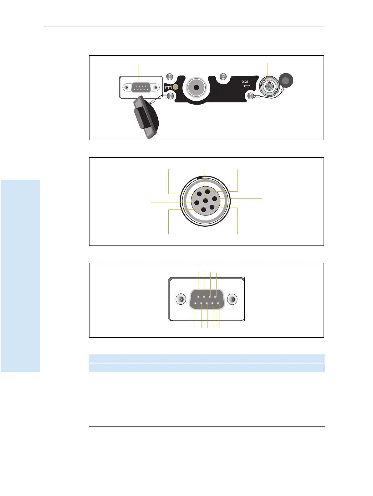
19.1Port 1 and 2 connectors
Figure 19.1 Receiver serial ports
Figure 19.2 Port 1 connector pinouts
Figure 19.3 Port 2 connector pinouts
Pin Pinout function
Port 1 – 7-pin Lemo Port 2 – DB-9
1 Signal ground DCD
2 - Power ground RXD
3TXD TXD
4N/C DTR
5 N/C Signal ground
6 + Power in DSR
1
2
BARCODE S/N LABEL
Port 1
Port 2
71
3
6
4
2
5
Pins 9 8 7 6
Pins 5 4 3 2 1