Trimble R6/R7 GPS and Trimble R8 GNSS Receivers User Guide 69
Cables and Connectors 10
Trimble R7 GPS Receiver Operation
10.4GPS antennas and cables
The antenna that a receiver uses to collect satellite signals is sometimes called a GPS
antenna to distinguish it from a radio antenna. Radio antennas are used for
communication between receivers and external networks or systems.
Note – Older models of antennas, such as Choke Ring or Micro-Centered L1/L2, have
different power requirements. The Trimble R7 GPS receiver can adjust the antenna power
output when you designate the appropriate antenna in the GPS Configurator software. For
more information, see Antennas, page 25.
Connect the receiver to its GPS antenna using the yellow TNC connector. Use a coaxial
cable with a right-angle TNC plug at the antenna end.
6Power IN (+)
→
6 Power IN (+)
7 Serial data in
(RXD2)
←
7 Serial data out
(RXD2)
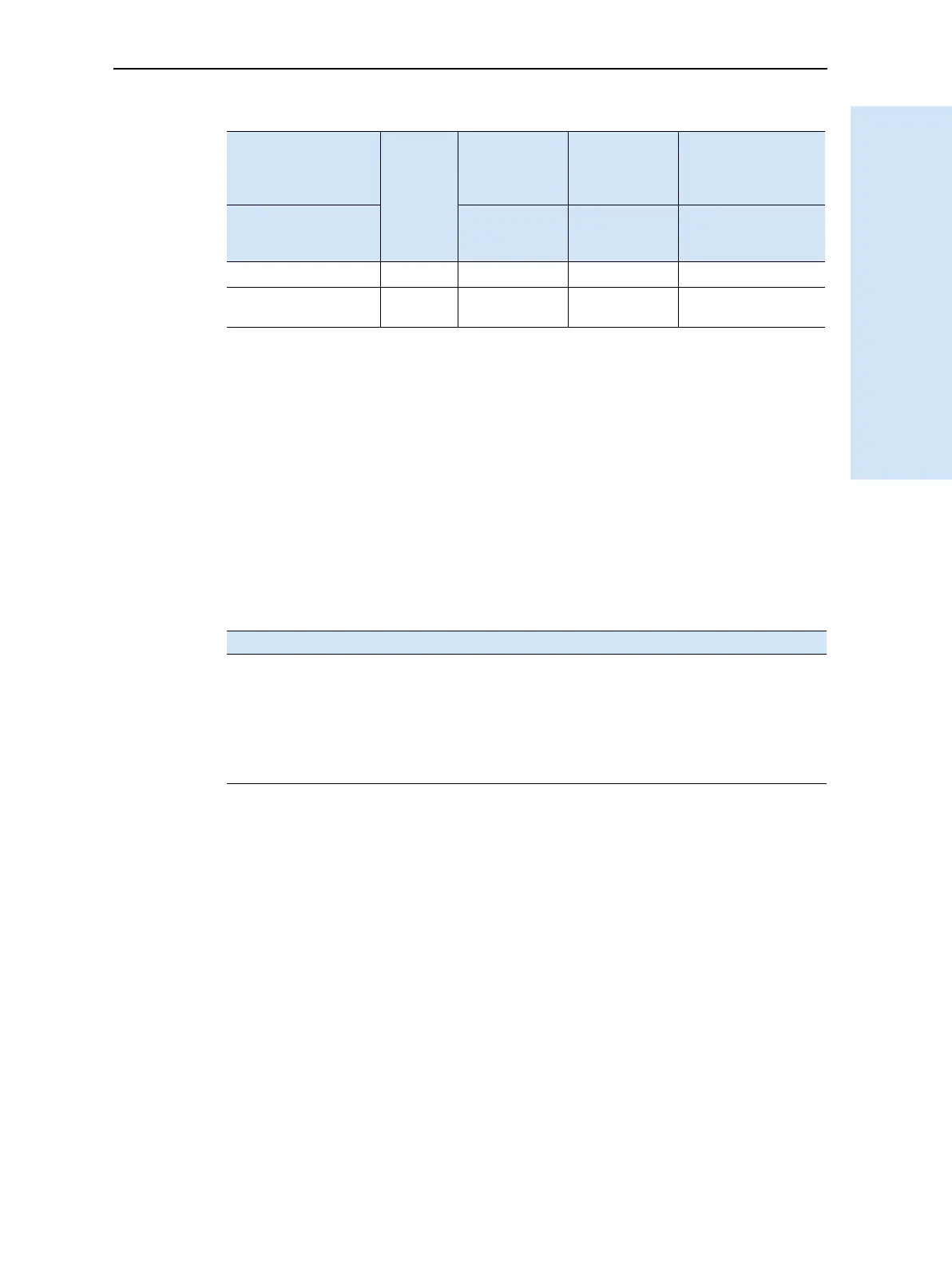
If the antenna cable length is … use …
up to 15 meters (45 feet) RG-58 cable
up to 30 meters (100 feet) RG-214 cable
over 30 meters (100 feet) one of the following:
• in-line amplifier
• semi-rigid coaxial cable
• a low-loss cable assembly
Table 10.3 Event marker/1PPS cable pinouts (Continued)
P1: Lemo 7-Pin
Port 2 Trimble R7
GPS receiver
Direction P2: BNC-F
connector
(1PPS)
P3: BNC-F
connector
(Event
marker)
P4: Lemo 7s
Port 2 extension
Pin Trimble R7 GPS
receiver
function
Pin Pin Pin Function