Trimble R6/R7 GPS and Trimble R8 GNSS Receivers User Guide 13
Setting up the Receiver 3
Trimble R7 GPS Receiver Operation
The TNC port connectors are color-coded for easy system setup. Connect the yellow
GPS antenna cable to the yellow TNC port marked GPS, and connect the blue Range
Pole antenna (RPA) cable to the blue TNC connector marked RADIO. For more
information on connecting the Trimble R7 GPS receiver, see the following sections in
this chapter.
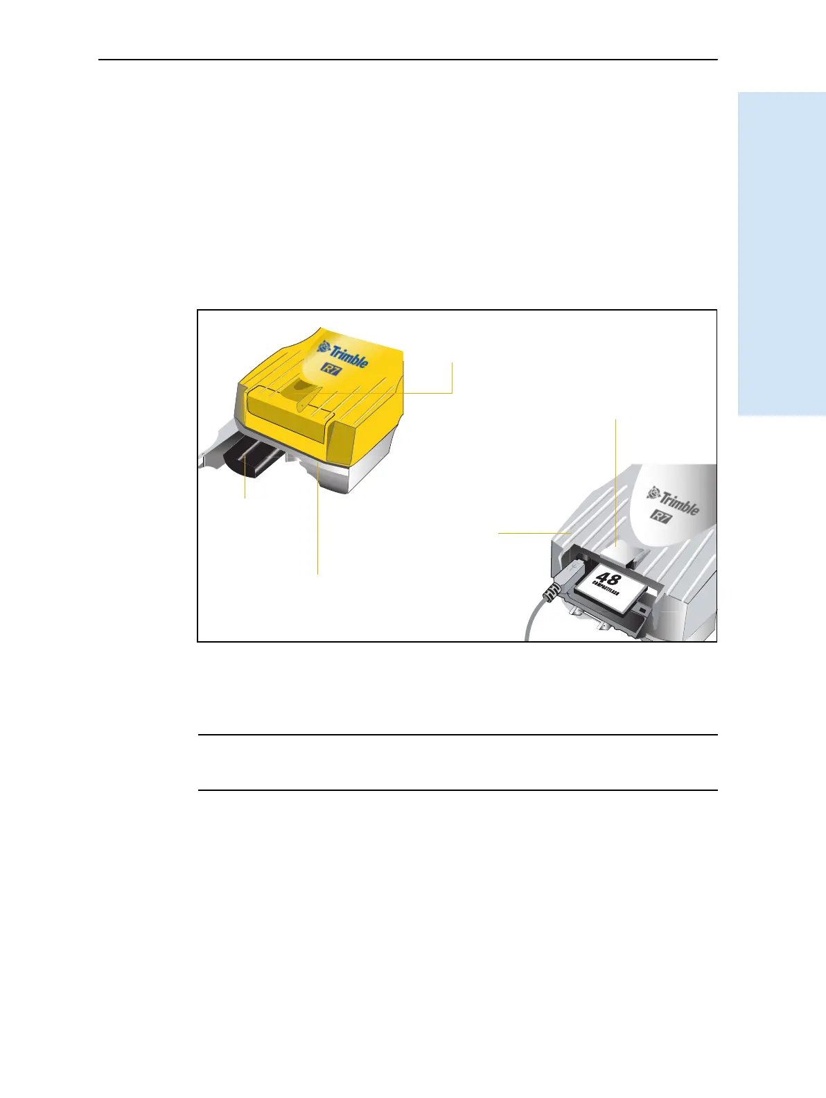
31.4 Bottom panel
Figure 3.5 shows the bottom panel of the Trimble R7 GPS receiver. This panel contains
the USB port, the CompactFlash port, and the compartments for the two internal
batteries.
Figure 3.5 Bottom panel
The CompactFlash/USB door conceals the CompactFlash port and USB port. To open
the door, push down the catch on the front panel.
C
WARNING – When there is no USB cable connected, or when using the receiver in a harsh
environment, keep this door closed to keep moisture, dust, and dirt out of the ports. The
temperature rating of the receiver applies only when all doors on the receiver are closed.
CompactFlash port
USB port
Internal battery
compartment
Internal battery
CompactFlash/
USB door