3 Setting up the Receiver
12 Trimble R6/R7 GPS and Trimble R8 GNSS Receivers User Guide
Trimble R7 GPS Receiver Operation
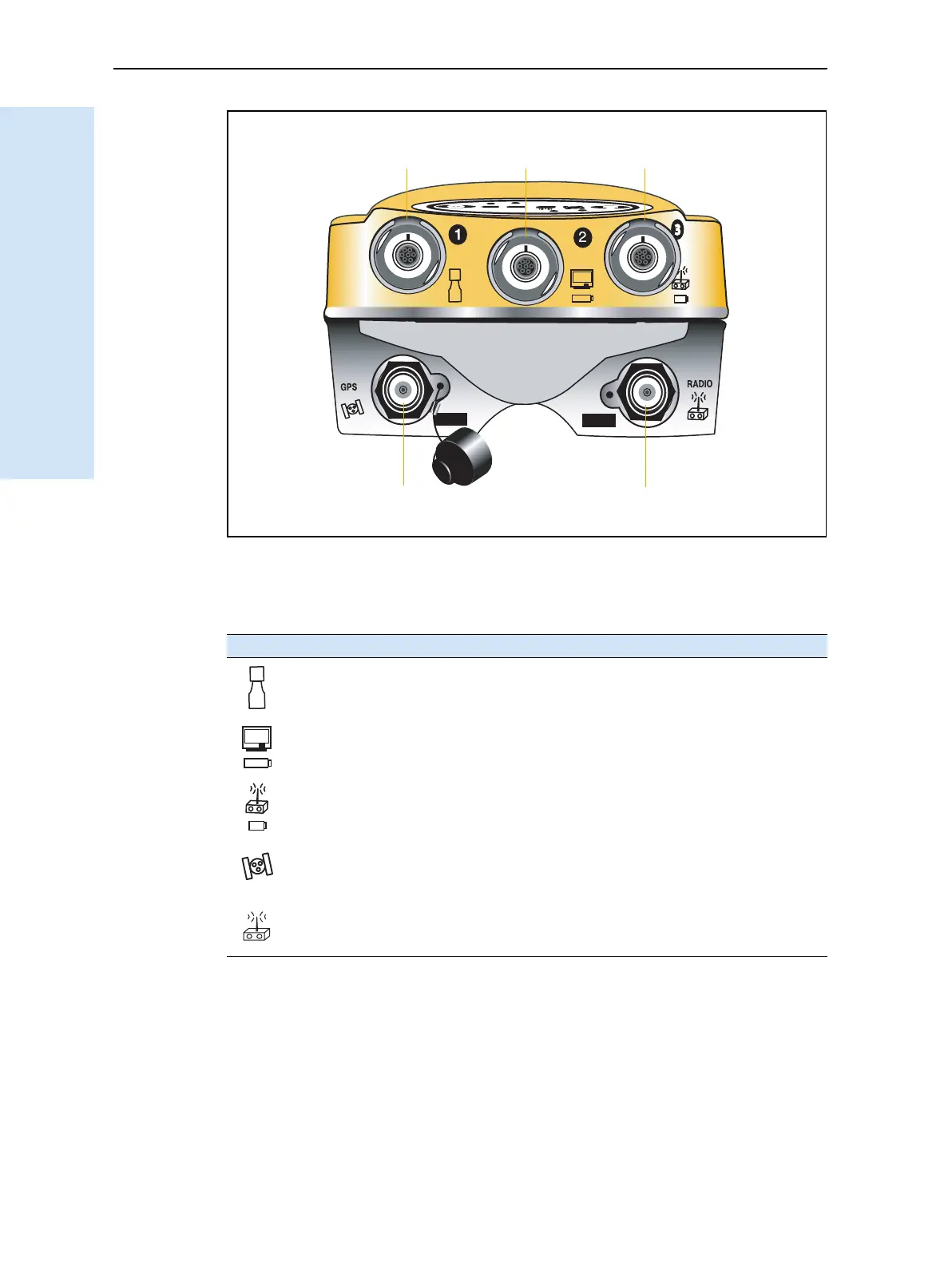
Figure 3.4 Top panel
Each port on the top panel is marked with an icon to indicate its main function, as
shown below.
The power/serial data ports are all 7 pin 0-shell Lemo connectors. Both Port 2 and
Port 3 can accept external power. For more information, see Default settings, page 60
and Cables and Connectors, page 65.
Icon Name Connections
Port 1 Trimble controller, event marker, or computer
Port 2 Power in, computer, 1PPS, or event marker
Port 3 External radio, power in
GPS GPS antenna
RADIO Radio communications antenna
Power/serial data ports
TNC ports
123
GPS antenna Radio antenna