Trimble R6/R7 GPS and Trimble R8 GNSS Receivers User Guide 121
Cables and Connectors 19
Trimble R6 GPS and R8 GNSS Receiver Operation
19.2Power/serial data cables
The data-I/O cable, (P/N 18532) is supplied with the receiver.
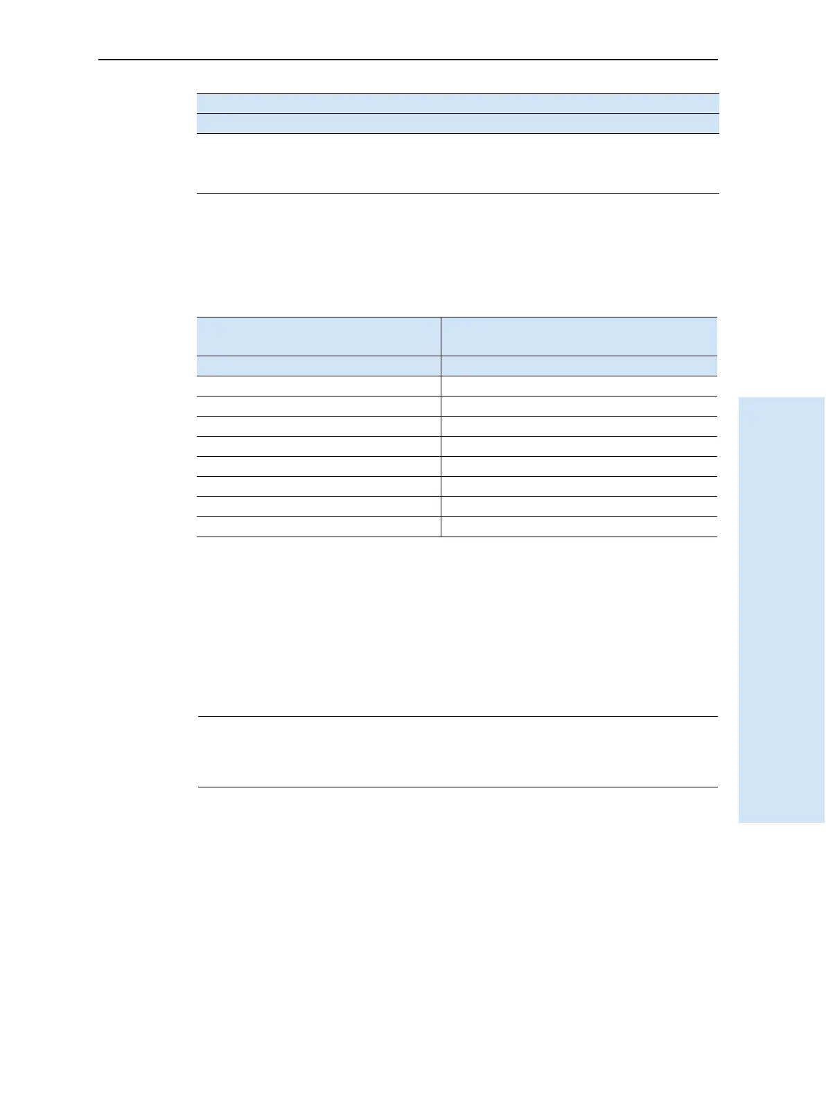
Note – Table 19.1 assumes that the cable is attached to the connector labeled Port 2.
This data cable may be used for firmware upgrades and other computer functions with
the receiver. Power must be supplied to the receiver through Port 1, or from the
internal battery.
Note – This pinout information also applies to the power/serial data cable (P/N 32345),
which is optional for use with the receiver. This cable can be used for firmware upgrades
through Port 1, while also supplying external power.
C
CAUTION – Cable (P/N 53107) supports the connection between the receiver and the
Multi Battery Adaptor. The cable carries power only and must not be used in any other
manner. Damage to equipment can occur if this cable is not used in conjunction with the
receiver and the Multi Battery Adaptor.
7TRXD RTS
8N/A CTS
9 N/A Ring indicator
Table 19.1 Data-I/O cable pinouts
DB-9 Female
9-pin
DB-9 Female
9-pin
Pin Function Pin Function
1-6 DCD5_232 4 DTR5_232
2 RX5_232 3 TX5_232
3 TX5_232 2 RX5_232
4 DTR5_232 1-6 DCD5_232
5 GND 5 GND
7 RTS5_232 8 CTS5_232
8 CTS5_232 7 RTS5_232
9 no connection RI5_232 9
Pin Pinout function
Port 1 – 7-pin Lemo Port 2 – DB-9