13 Setting up the Receiver
82 Trimble R6/R7 GPS and Trimble R8 GNSS Receivers User Guide
Trimble R6 GPS and R8 GNSS Receiver Operation
13.1Parts of the receiver
All operating controls on the receiver are located on the front panel. Serial ports and
connectors are located on the bottom of the unit.
131.1 Front panel
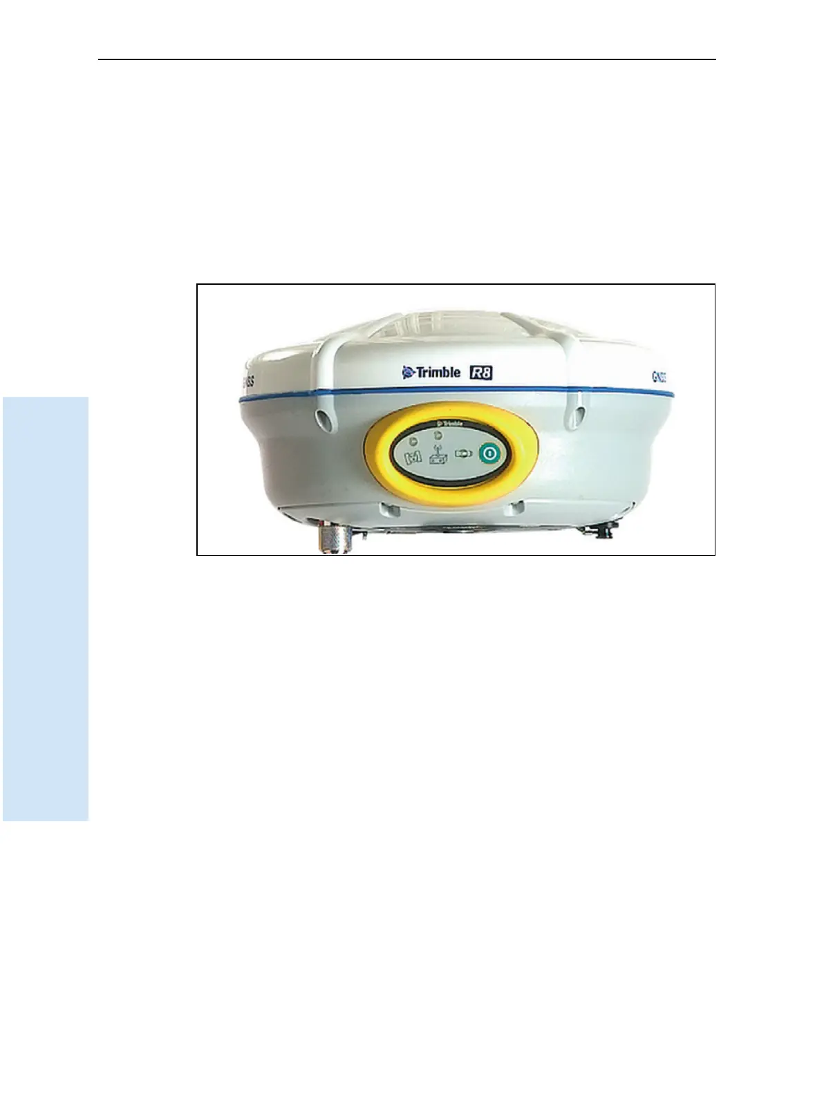
Figure 13.1 shows a front view of the Trimble R8 GNSS receiver. The front panel on the
Trimble R6 GPS receiver is identical. The panel contains the three indicator light
emitting diodes (LEDs), and the power button.
Figure 13.1 Trimble R8 GNSS receiver front panel
The power button controls the receiver’s power on or off functions.
The indicator LEDs show the status of power, satellite tracking, and radio reception.
For more information, see LED behavior, page 90.
131.2 Lower housing
Figure 13.2 shows the lower housing of the Trimble R8 GNSS receiver. The lower
housing on the Trimble R6 GPS receiver is identical. The lower housing contains the
two serial ports, one TNC radio antenna or GSM antenna connector (depending on the
internal communication module ordered), the removable battery compartment and
the 5/8-11 threaded insert.