Trimble R6/R7 GPS and Trimble R8 GNSS Receivers User Guide 83
Setting up the Receiver 13
Trimble R6 GPS and R8 GNSS Receiver Operation
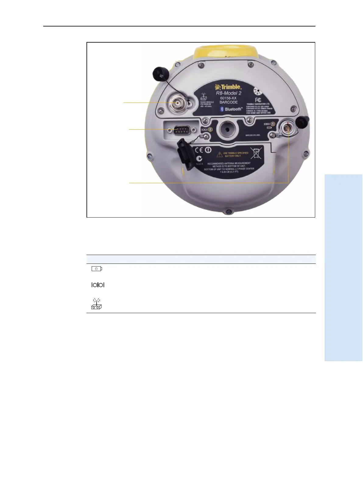
Figure 13.2 Trimble R8 GNSS receiver lower housing
Each port or connector on the receiver is marked with an icon to indicate its main
function as shown below.
Port 1 is a 7-pin 0-shell Lemo connector that supports RS-232 comms and external
power input. Port 1 has no power outputs.
Port 2 is a DB-9 male connector that allows for full 9-pin RS-232 comms. Port 2 does
not support power in or out. For more information, see Chapter 18, Default Settings
and Chapter 19, Cables and Connectors.
The TNC connector is for connecting a radio antenna to the receiver internal radio. A
whip “rubber duck” antenna is supplied with the system for units with internal UHF
radios. This connector is not used if you are using an external UHF radio or GSM.
Icon Name Connections
Port 1 Device, computer, external radio, power in
Port 2 Device, computer, external radio
RADIO Radio communications antenna
Port 1
Port 2
Radio
antenna
connection