3 Setting up the Receiver
10 Trimble R6/R7 GPS and Trimble R8 GNSS Receivers User Guide
Trimble R7 GPS Receiver Operation
3.1 Parts of the receiver
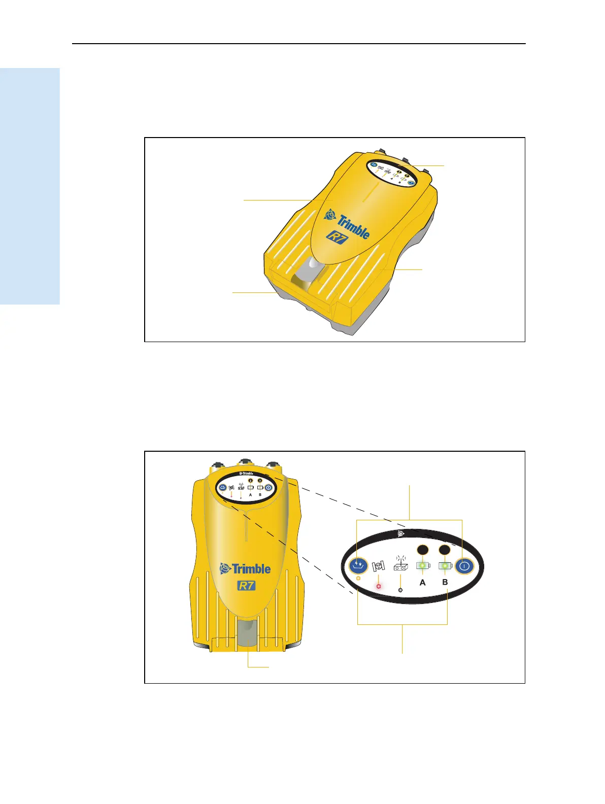
All operating controls, ports, and connectors on the receiver are located on its four
main panels, as shown in Figure 3.1. This section provides a brief overview of the
features of each of these panels.
Figure 3.1 Panels on the Trimble R7 GPS receiver
31.1 Front panel
Figure 3.2 shows the front panel of the Trimble R7 GPS receiver. This panel contains
the five indicator LEDs, the two buttons, and the catch for the CompactFlash/USB
door.
Figure 3.2 Front panel
Bottom
panel
Top
panel
Front
panel
Rear
panel
USB door catch
2
3
t
Buttons
Indicator LEDs
CompactFlash/