Trimble R6/R7 GPS and Trimble R8 GNSS Receivers User Guide 11
Setting up the Receiver 3
Trimble R7 GPS Receiver Operation
The two buttons control data logging, data management, power, and settings. For more
information, see Button functions, page 28.
The indicator LEDs show the status of logging, power, satellite tracking, and radio
reception. For more information, see LED behavior, page 29.
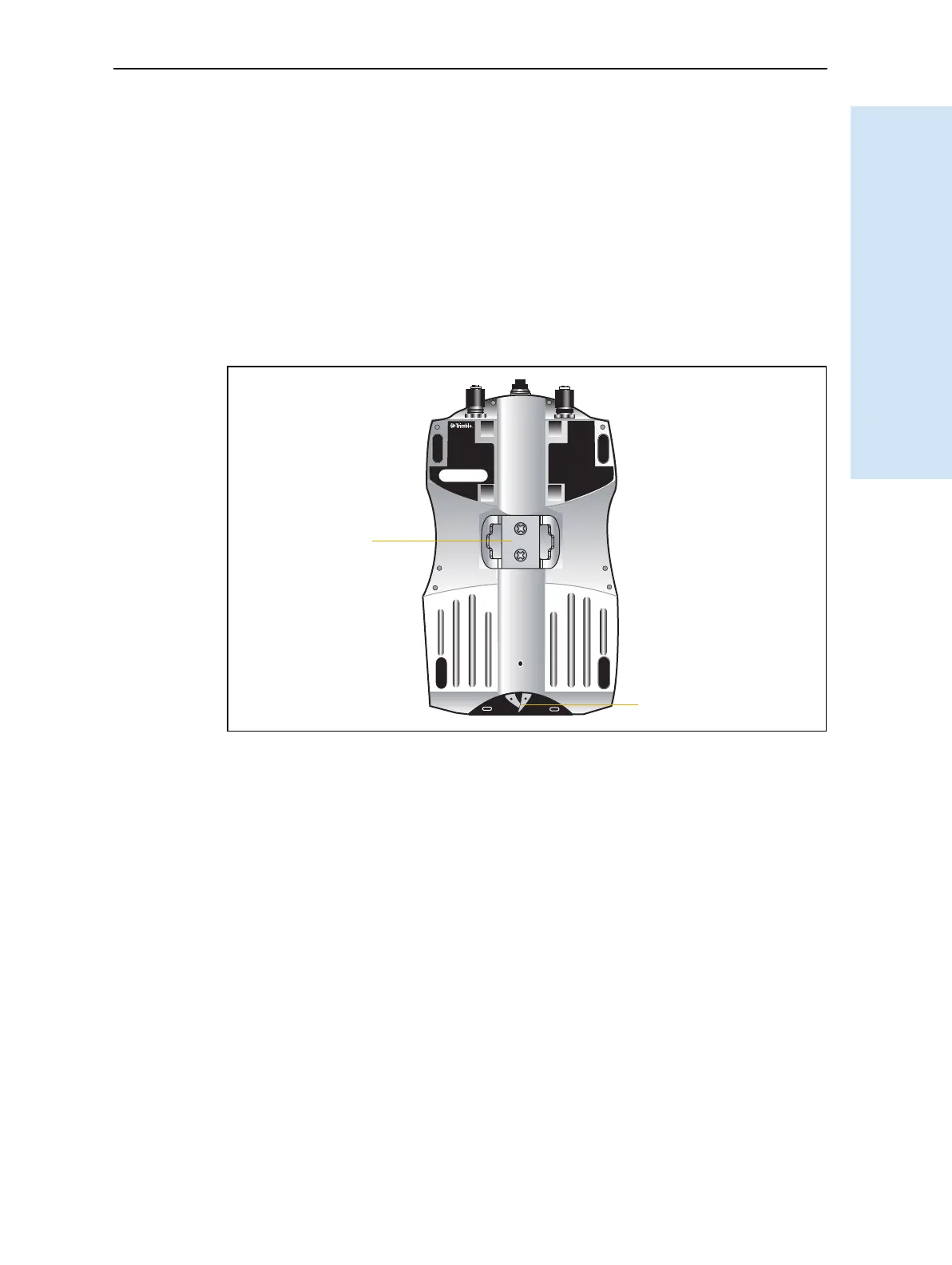
31.2 Rear panel
Figure 3.3 shows the rear panel of the Trimble R7 GPS receiver. This panel contains a
slot for attaching the receiver catch lock, and the catches for the two battery
compartments on the bottom panel. The catch lock should already be attached to your
receiver.
Figure 3.3 Rear panel
To mount the receiver on a pole, attach the receiver bracket to the pole and then insert
the catch lock into the bracket. For more information, see Pole-mounted setup,
page 16.
31.3 Top panel
Figure 3.4 shows the top panel of the Trimble R7 GPS receiver. This panel contains the
three power/serial data ports and (TNC) ports for GPS and radio antenna connections.
compartment catches
Receiver
catch lock
Battery