19 Cables and Connectors
122 Trimble R6/R7 GPS and Trimble R8 GNSS Receivers User Guide
Trimble R6 GPS and R8 GNSS Receiver Operation
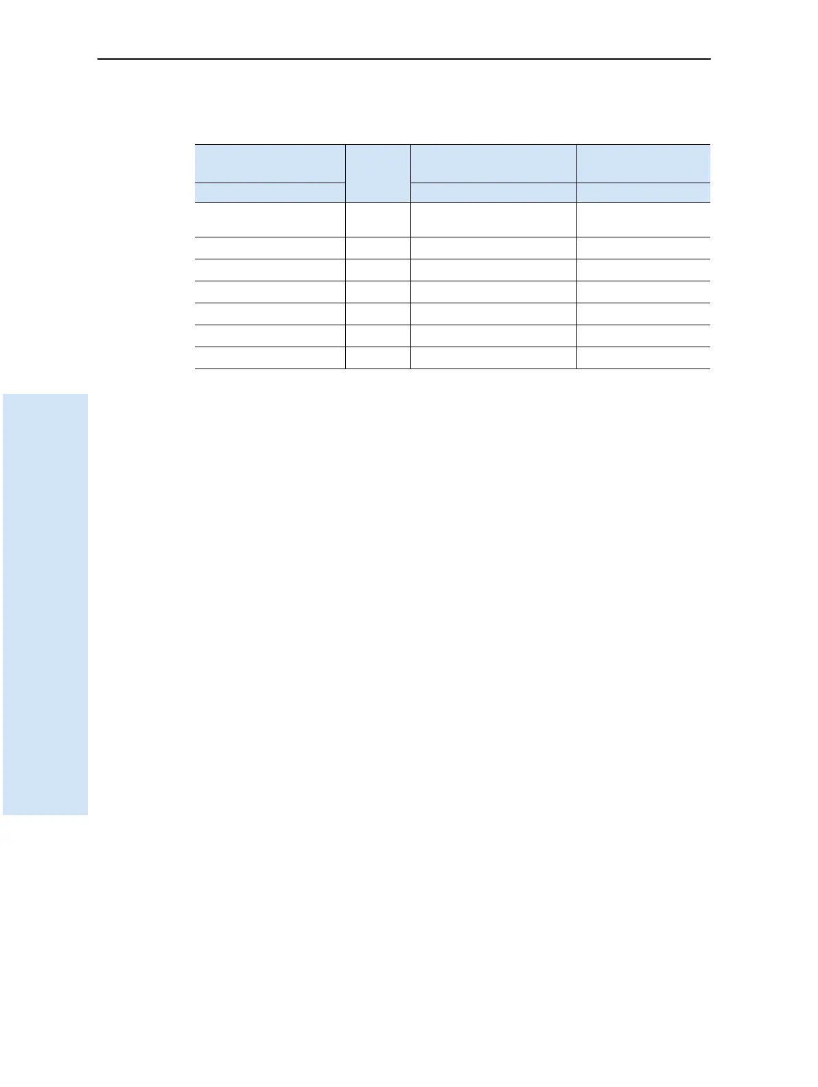
Note – Table 19.2 assumes that the cable is attached to the connector labeled Port 1.
Table 19.2 Power/serial data cable pinouts
Lemo 0-shell connector
7-Pin
Direction DE9-F connector
7 Cond
Power lead
2 Cond
Pin Function Pin Color Function Color Function
1 GND
↔
5BrownSignal
ground
2 GND
→
Black V-OUT
3TX3_232
→
2OrangeTXD
4RTS/TXD
→
8Blue RTS
5CTS/RXD
←
7 Green CTS
6PWR_IN
←
Red Power IN (+)
7 RX3_232
←
3 Yellow TXD