10 Cables and Connectors
68 Trimble R6/R7 GPS and Trimble R8 GNSS Receivers User Guide
Trimble R7 GPS Receiver Operation
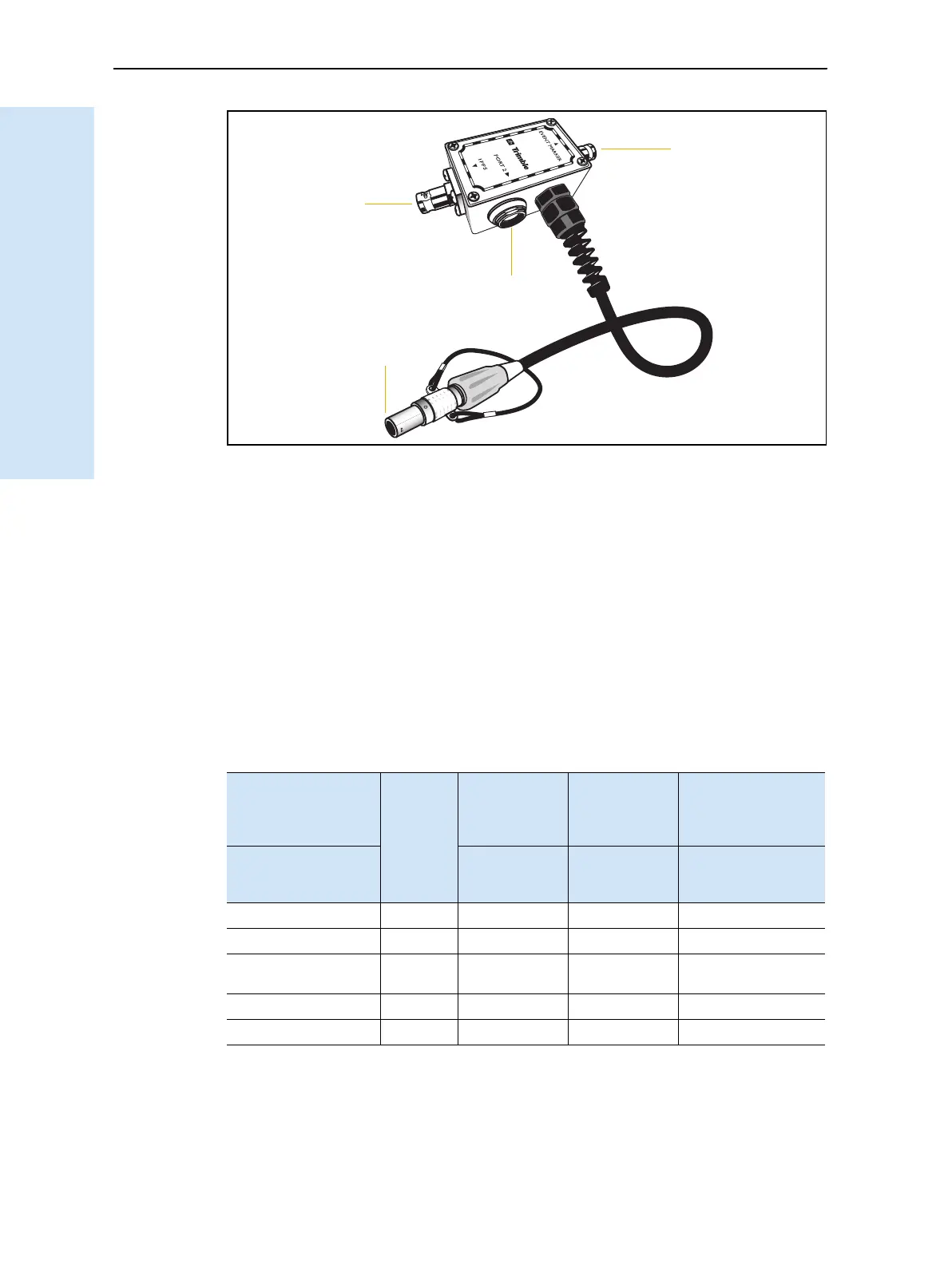
Figure 10.3 Event marker/1PPS cable
In addition, the breakout box includes a Lemo 7-pin connector to extend serial
communications and/or power on Port 2. Because the BNC connectors are used to
service the event marker and 1PPS features, pins 4 (1PPS) and 5 (Event Marker) are
inactive on the Lemo connector.
For Port 2 pinouts, see Port 1, 2, and 3 connectors, page 66. For more information on
1PPS input and event marker output, see Chapter 11, Event Marker Input and 1PPS
Output.
Tab le 10 .3 gives pinout information for the event marker/1PPS cable, which is supplied
with the Trimble R7 GPS receiver. The event marker/1PPS cable is only used with the
Trimble R7 GPS receiver connectors labeled Port 1 ( for event marker output) and
Port 2.
Table 10.3 Event marker/1PPS cable pinouts
P1: Lemo 7-Pin
Port 2 Trimble R7
GPS receiver
Direction P2: BNC-F
connector
(1PPS)
P3: BNC-F
connector
(Event
marker)
P4: Lemo 7s
Port 2 extension
Pin Trimble R7 GPS
receiver
function
Pin Pin Pin Function
1 Signal ground
←
1 Signal ground
2GND
→
GND GND 2 GND
3 Serial data out
(TXD2)
←
3 Serial data in
(TXD2)
4 1PPS
←
Center pin 4 No Connect
5 Event Marker
↔
Center pin 5 No Connect
P4
P3
P1
P2
(Event marker)
(1PPS out)
(To Port 2)
(Port 2 extension)