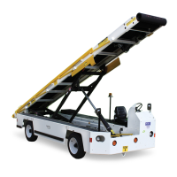
Operation Mobile Belt Loader Model 660
Operation Manual
CD397-Oper Operation - 1 - 5
1.4.2.2Diesel-Deutz2.9L
The diesel engine is a heavy duty, industrial type four cycle with Common Rail Direct Injection
(CRDI).
1.4.3Transmission
The transmission is a GM 4L70 automatic with abuse protection valve body and torque converter.
1.4.4DriveShaft
The tractor’s drive shaft is an automotive type with double universal joints and slip yokes.
1.4.5DriveAxle
The rear (drive) axle is a Dana Model 60 with full floating axles and drum brakes.
1.4.6SteerAxle
The front (steer) axle is a Brierton with disc brakes.
1.4.7Brakes
1.4.7.1Hydraulic
Hydraulic service brakes are provided on all four wheels. The master cylinder is mounted on the
rear side of the front bumper. Pressure is transmitted to all four brake assemblies by depressing
the brake pedal.
1.4.7.2ParkBrake
A cable-actuated parking brake is provided, and is engaged by the brake lever mounted to the
right of the seat in the operator’s compartment.
1.4.8Chassis
The 660 Mobile Belt Loader is built on a heavy duty chassis which includes the power package
and running gear. The chassis has a 110 in. (279.4 cm) wheel base, formed steel channel frame
supported by the front and rear axles.
1.4.9Body
The vehicle's body panels are formed from 3/16in. (0.476 cm) steel and bolted to the chassis.
The front and rear fenders are installed with standard mounting hardware and are independently
replaceable from the center section.
The 3/16 in. (0.476 cm) formed steel body panels are fabricated
in 6 sections (3 sections on right
and 3 sections on the left side of vehicle). The front and rear fenders are mounted separately
from the center section and may be replaced independently.
A body panel support structure is integrated in chassis which incorporates the pivot and attaching
po
ints for the front and rear lift frames and the lift cylinders.
Protective rub strips can be attached to the full len
gth of both sides of the vehicle to provide fur-
ther protection for the body panels.