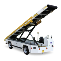
Operation Mobile Belt Loader Model 660
Operation Manual
CD397-Oper Operation - 1 - 7
Engine controls are mounted in the operator’s compartment instrument panel and include hour
meter, ignition switch, and light switches.
1.4.12ElectricalSystem
Electrical power is supplied by an alternator, belt-driven, mounted on the side of the engine. The
system is a 12-volt, direct current system with negative ground.
All operating circuits are wired through the ignition swit
ch and are protected by circuit breakers.
1.4.13HydraulicSystem
1.4.13.1GeneralHydraulicsOperation
The hydraulic schematic (see the Maintenance Manual) represents an open center system that
supplies power to raise and lower the conveyor and to drive the conveyor belt.
Hydraulic power is supplied by a hydraulic pump,
belt- or gear-driven, mounted on the engine.
The pump supplies 9 gpm (34.08 lpm) at 1500 rpm to raise and lower the conveyor and to drive
the conveyor belt.
Both lift cylinders are locked in any position by hold
ing valves.The orbital motor has incorporated
a counterbalance and cushion valve in the circuit.
All hydraulic hose connections are Ga
tes brand Mega Crimp. Mega Crimp connectors join the
reinforcing wire inside the hose. This is more reliable than the grip on the rubber of the hose.
Mega Crimp connections are plated to resist damage from corrosion. The Mega Crimp connec-
tions are rated at 3000 psi (US) (20.68 MPa or 204.14 atm) working pre
ssure. All hydraulic hoses
are Gates brand Mega 3000 rated for 3250 psi (22.41 MPa or 221.15 atm) working pressure. All
pipes are constructed from Benteler hydraulic piping rated for 3000 PSI (20.68 MPa 204.14 atm)
working pressure.
Hydraulic fluid is drawn from the hydraulic oil reservoir to the hydraulic pu
mp at a rate of six gals
(22.71 l) to ten gals (37.85 l) per minute into a pipe manifold. From the pump, fluid is directed to a
pressure-compensated flow divider valve in the valve manifold, located under the driver’s seat.
The pressure-compensated flow divider valve separates the hydraulic system into a steering and
braking section and a lift cylinder and conveyor motor section.
1.4.13.2SteerandBraking
The pressure-compensated flow divider valve provides a constant 2 gpm (7.57 lpm) of oil flow to
the Steering / Braking portion of the hydraulic system. Hydraulic fluid pressure for the steering
and braking section is limited by a pressure relief valve, set at 1000 psi (6.9 MPa or 68.05 atm),
in the hydraulic manifold. Hydraulic oil then flows to the hydraulic brake system assist valve via
port, then to the hydraulic steering motor.
Fluid from the hydraulic brake system assist valve and the hydra
ulic steering motor return to the
manifold. This fluid then exits the manifold. Fluid passes through the return line hydraulic filter
before returning to the hydraulic oil reservoir.
When the brake pedal is depressed, pressurized hydraulic f
luid enters the hydraulic brake sys-
tem assist valve and exerts pressure on a spring
loaded check valve, closing the hydraulic fluid