144
Do not attempt to over-tight the adjuster bolt, beyond
the maximum and minimum position, to prevent internal
damage.
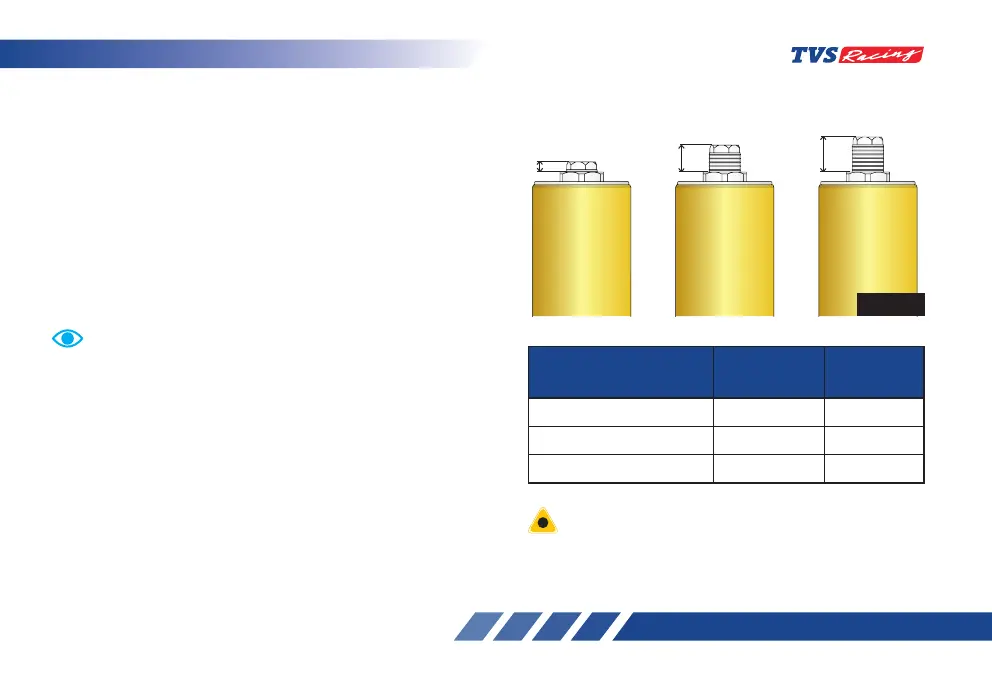
1
st
groove - hard
suspension
5
th
groove - Standard
position
7
th
groove - soft
suspension
A
A
A
Spring Preload
Distance ‘A’
(in mm)
Groove
position
Standard 14 5
Maximum 4 1
Minimum 19 7
Fig. 42
Always set the spring loads in both fork legs equally to
obtain optimum suspension performance.
Each fork leg is provided with a spring ‘PRELOAD’
adjusting bolt. Also the right leg is provided with a
‘COMPRESSION’ damping force and left leg is provided
with ‘REBOUND’ damping force. This adjustment can be
done through the damping adjusting screw.
• The spring preload setting is determined by the
distance ‘A‘ or number of grooves. Shorter the
distance ‘A’ or number of grooves indicates higher
preload (ref. Fig. 42).
- To lower the preload, rotate the preload
adjusting bolt in clockwise direction.
• Higher the distance ‘A’ or number of grooves
indicates lower preload.
- Rotate the preload adjusting bolt in
anti-clockwise to higher the preload.