5-12
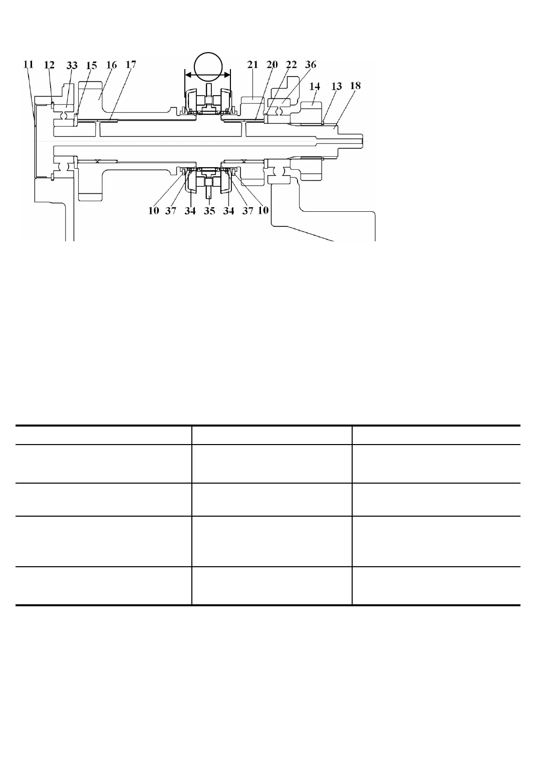
(3) Disassembly of reverse shaft and related parts.
a. Pull out the snap ring(13)next to the creep gear(14)
b. Remove the bearing(36 and 33)
c. Remove the washers(15 and 22), needle bearings(17 and 20), synchro-hub comp,(35),
etc. synchro-cup(34) can be taken off as an assembly with gears(16 and 21).
d. Remove the snap ring(37) and detach the synchro-cup.
1.2 INSPECTION
Before and after disassembly, inspect each part for points mentioned below, and replace if necessary.
Inspection items Standard values Usable limits
Backlash of each gear
(measured in meshed condition)
0.1 - 0.2 ㎜
(0.004-0.008 in)
0.3 ㎜
(0.011 in)
Stepped wear of teeth 0 ㎜
(0 in)
0.3 ㎜
(0.011 in)
Assembled width of
synchromesh assembly
Dimension A
51.17 ㎜ (50.746~51.27)
(2.015 in)
-
Synchro-hub thrust for shifting
Neutral-Engaging
13.0-18.8 Kgf
(28.7-41.5 lbs)
9.5 Kgf
(20.9lbs)
-Inspect bearings such as ball bearings and needle bearings for abnormalities in rotation such as
irregularity, hitching, etc. by turning them with pressure applied by hand. Replace defective ones.
-Seriously worn or damaged parts should also be placed.
(13) Snap ring
(14) Creep gear
(17) Needle bearing
(18) Reverse shaft
(20) Needle bearing
(33) Bearing
(34) Synchro-cup
(35) Synchro-hub comp
(36) Bearing
(37) Snap ring
Fig.5-25
A