your position is our focus
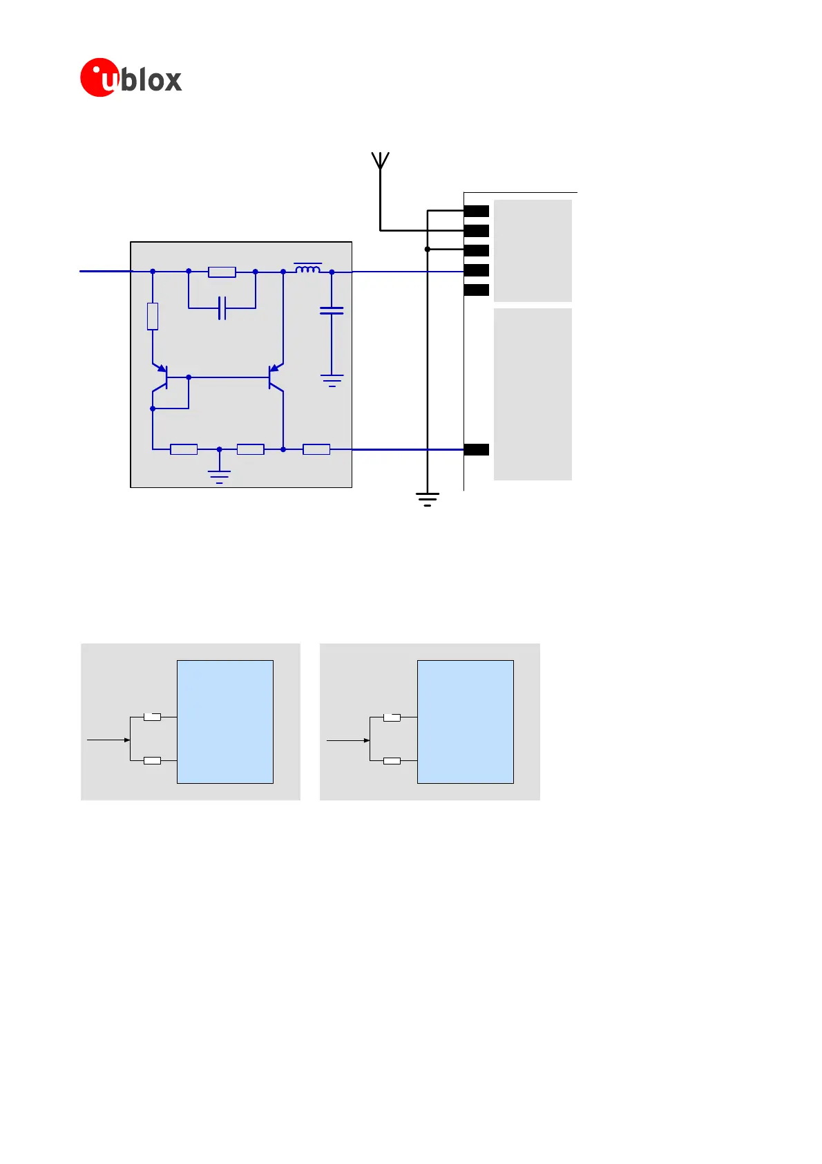
Active Antenna
ADDET_N
GND
RF_IN
V_ANT
VCC_RF
GND
V_ANT
Antenna
Supply in
C2
FB1
R1
R2
Analog GND
R3 R4 R5
T
PN
T2
PNP
1
P
ADDET_N
C1
TIM/LEA
Figure 65: Schematic of open circuit detection
AADET_N is assigned to different pins for TIM-4R and the other variants of TIM-4x. On TIM-4x, AADET_N is
assigned to pin 27 (see Figure 65). On TIM-4R, AADET is assigned to pin 30 since pin 27 is used for the SPI
interface.Incaseofdesigns,whereeitheraTIM-4xor
aTIM-4Rshallbepopulated,alayoutfortwooptional0-
Ohmresistorstopin27and30shallbeprovided(seeFigure66).
TIM-4R
AADET_N
27 (MISO)
30 (AADET_N)
TIM-4x
w/o TIM-4R
AADET_N
27 (AADET_N)
No resistor
OR
No resistor
OR
30 (Reserved/
GPSMODE12)
Figure 66: Connection of "Open Circuit Detection" signal to AADET_N input
GPSModules-SystemIntegrationManual(SIM)(incl.ReferenceDesign) ReceiverDescription
GPS.G4-MS4-05007-A1
Page 77
 Loading...

