21
3-2-1. RF generator mounting structure
This product has a structure that can be rack mounted. For drilling installation holes in the rack,
refer to the included outline drawing.
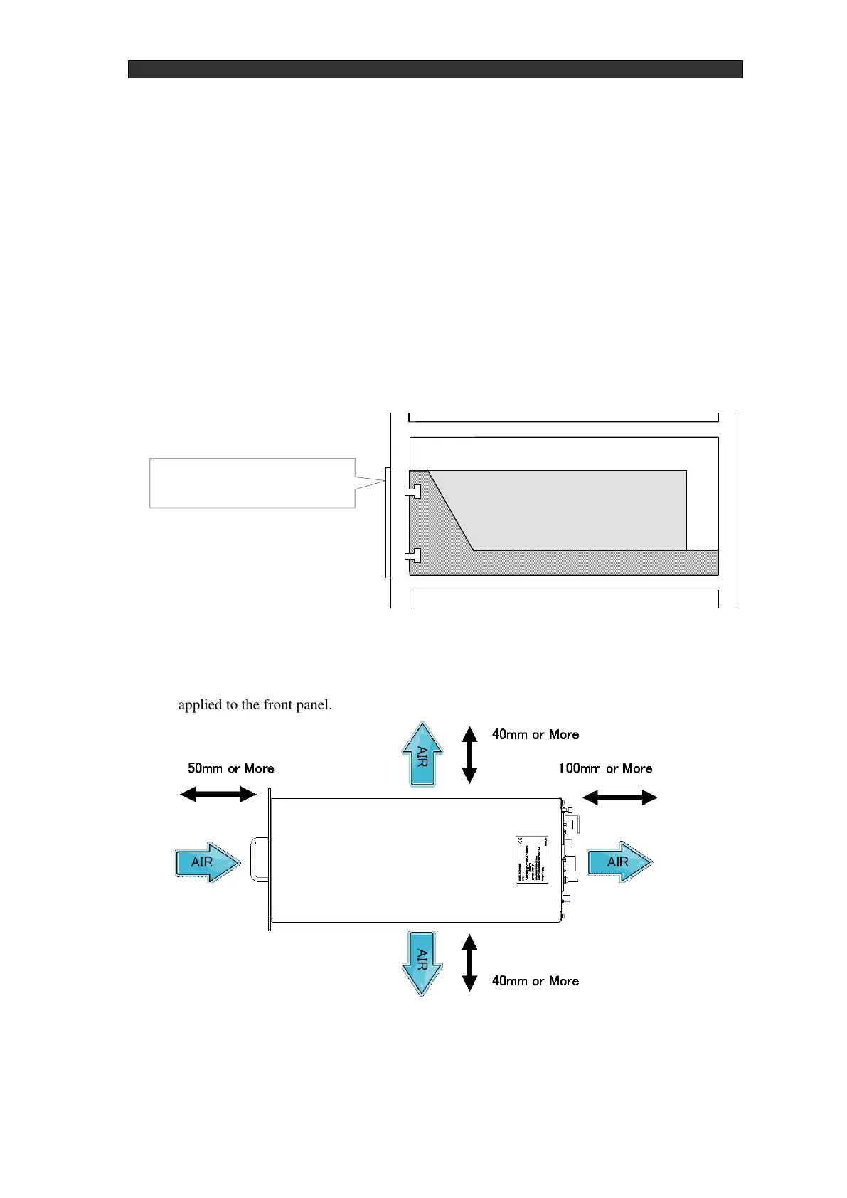
The RF generator's front panel is not designed to bear the RF Generator's weight. In mounting
the RF generator, ensure that undue force is not exerted on the front panel. See "Figure 3-1 RF
Generator installation example". Also provide ample clearance in the area around the RF
Generator for air intake. When using the RF Generator in a rack mount, ensure there can be ample
ventilation so the temperature inside the rack does not exceed the specified temperature. If the RF
Generator is run at a temperature outside specifications, an alarm will be output and there is a risk
of damage.
Fashion the rack so that the RF generator is supported from below and no undue force is
applied to the front panel.