69
6. Matching Adjustment
6-1. Matching adjustment overview
6-1-1. Matching fundamentals
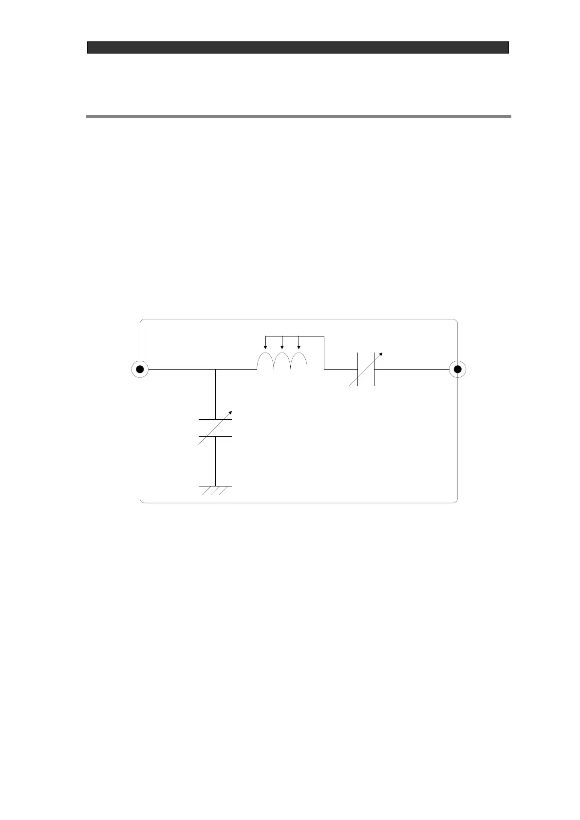
As shown in the basic matching circuit figure below, the matching box consists of the TUNE
variable capacitor (C1), the MATCH variable capacitor (C2), and a coil (L). The TUNE variable
capacitor primarily serves to terminate at 50 Ω, and the MATCH variable capacitor primarily
serves for phase correction. The load impedance is matched to the RF generator's output
impedance of 50 Ω by these variable capacitors, thereby becoming able to efficiently supply power
to the load.
6-1-2. Matching adjustment
① Turn on RF output and increase the setting value until the Pf value is about 70% to 80% of the
maximum reflected wave rating. In this state, manually move the TUNE/MATCH variable
capacitors and search for the point that experiences discharge. * If there is no discharge, turn off
RF output, and make adjustments such as changing the gas pressure or changing the number of
coil turns inside the matching box, and then search for the point that experiences discharge.