5-1-3. Remote operation (external control operation) method
① Operation mode menu selection
On the P2 control mode selection screen, change the settings to "RFOP=ANALOG" and
"AMOP=ANALOG".
For the standalone controller type, the above settings are automatically set when the
controller is removed.
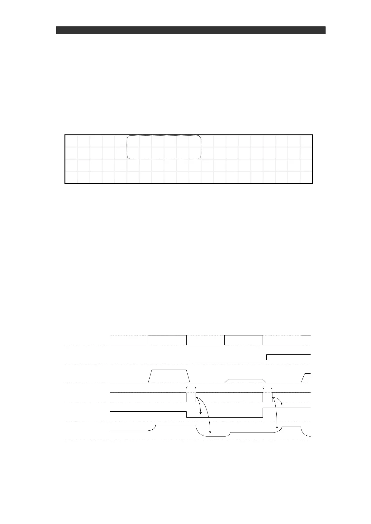
Figure 5-7 Control mode selection screen (P2)
② Output settings
Input external command voltage via the RF generator's EXT.CONT connector.
After the above voltage has been input, RF with the set power is output by inputting the
RF-ON command via the EXT.CONT connector. For the EXT.CONT connector pin
assignments, see "External control (EXT.CONT) pin assignments".
③ Analog preset operation setting
The analog preset operation starts when the motor strobe signal is input as one-shot signal
input from closed to open when RF is off.
Set the range of the pulse width of the above one-shot pulse signal between 100 ms and 1 s.
If the pulse is less than 100 ms or greater than 1 s, stable operation may not be possible. We
recommend a 500 ms one-shot pulse signal for the most stable operation possible.