27
3-4. System wiring
3-4-1. Cable connections
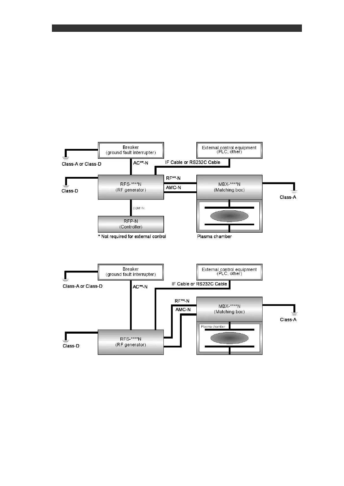
First check the connector names and dedicated cables between each unit, then see "Figure
3-4/Figure 3-5 System wiring diagram" and connect the cables. See "Table 3-3 Cable list" for the
cables used. Please prepare the wiring between the matching box and the chamber and the GND
wiring yourself.
* Ground the RF generator with Class D grounding.
* Ground the matching box with Class A grounding.
* The RFP-N and CONT-N cables are not used for the built-in controller type and when not using
a controller.
* To prevent breaking cables and deterioration when laying down cables, ensure a bending radius
of 300 mm or higher and take care so that cables are not repeatedly bent when laid down.