Do not connect an RF Generator with a different specification to the matching box and
do not input power that exceeds the maximum transmission power under any
circumstances.
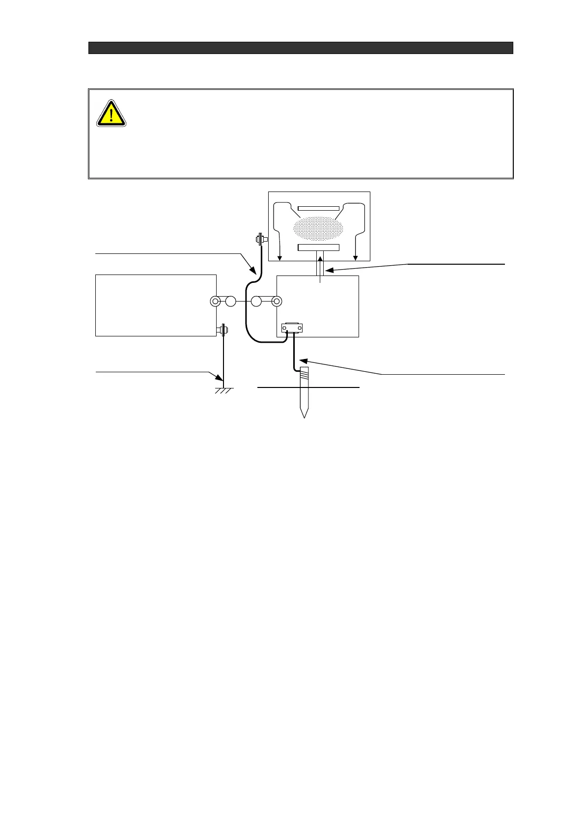
3-5. About the interlock
This product's interlock determines whether or not the RF generator connection and the
equipment status is at the minimum level where output can be turned on. Do not use this interlock
mechanism for the purpose of turning RF on and off. The interlock is detected in the locations
listed below.
① External interface connector "EXT.CONT" pins 16-17
② RF generator RF output coaxial connector section
③ Matching box RF input coaxial connector section
④ Matching box maintenance panel section
For "EXT.CONT" pins 16-17, the included jumper connector short circuits pins 16 and 17
when shipped from the factory. As necessary, wire it into the external control circuit.
When the interlock is operating, "EXT.INTERLOCK" is displayed on the panel. If you want
to check parameters in this state, press the "ON" key while holding down both the "ESC" key
and the "ENT" key.