BATTERY CHARGER USER’S MANUAL PART- 2: THEORY OF OPERATION
MCEnPC23-REV.2.4 Page 6
1. THEORY OF OPERATION
The battery charger provides a fully regulated and Isolated DC output from the main AC input. The LCD show
continuously the battery charger status: DC Voltage, DC current, alarms ….
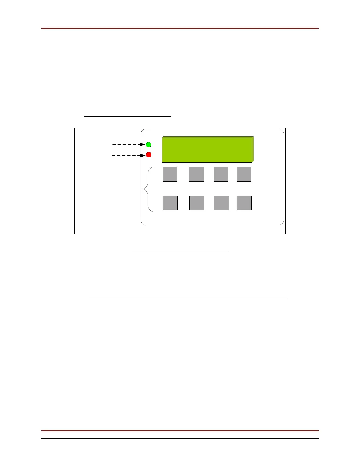
1.1 LCDDISPLAYANDKEYPAD
F1 F2 F3 F4
CONTROL, ALARM & COMMUNICATION
136.2V
10.5A
Equalize
A B C D
OR
ON AC
ALARM(S)
Each key corresponds
to above function as
described on the
following figures
Figure 1 : Battery charger home screen.
The LCD display and keypad provide very flexible and user friendly interface. The standard display is a high
visibility backlit two-line LCD display. Four (4) long life membrane switches are used as the keypad buttons.
1.2 GETTINGFAMILIARWITHBATTERYCHARGERLCDINTERFACE
All adjustable values and readings are displayed on the first line. Ex.: alarm activation status, voltage and current
readings…
On the second line, soft keys are used: each keyboard button’s function is displayed. The assignment of a button to a
function can change as needed by different menus or at different levels of access. The Red LED will blink when any
alarm occurs. A corresponding alarm message will also be displayed on the second line. If more than one message
is to be displayed then the messages will scroll sequentially.
All settings can be saved individually. The lit green LED indicates that the AC is on. The LCD back lighting will
turn off after 5 min of inactivity, if the power save function is selected. It will turn back on whenever a button is
pressed or any alarm occurs. The accuracy of all readings is 0.5% +/- 1digit.
 Loading...