Page 15 of 39 Rev. 13
2.3.3 Battery test
To start a battery test send (1000 in binary) to bit 3, 2, 1 and 0 respectively into the register (26 hex), (Refer to Note 21).
2.3.4 Alarm reset
To reset all alarms, send (1 in binary) into the register (5AL hex), (Refer to Note 3).
2.3.5 Messages
The charge LCD can display 4 different customer defined messages. These messages are stored into the RAM, starting
the address (60 hex).
Each message is coded with 16 bytes in ASCII.
Each message is associated to a logic signal coming from the customer provided contact
Addresses (57L hex), (58H hex) are used to associate the message to the logic (0-1) signal
Example
Message # 2 "Next On Off Exit” is to be associated with logic signal # 3
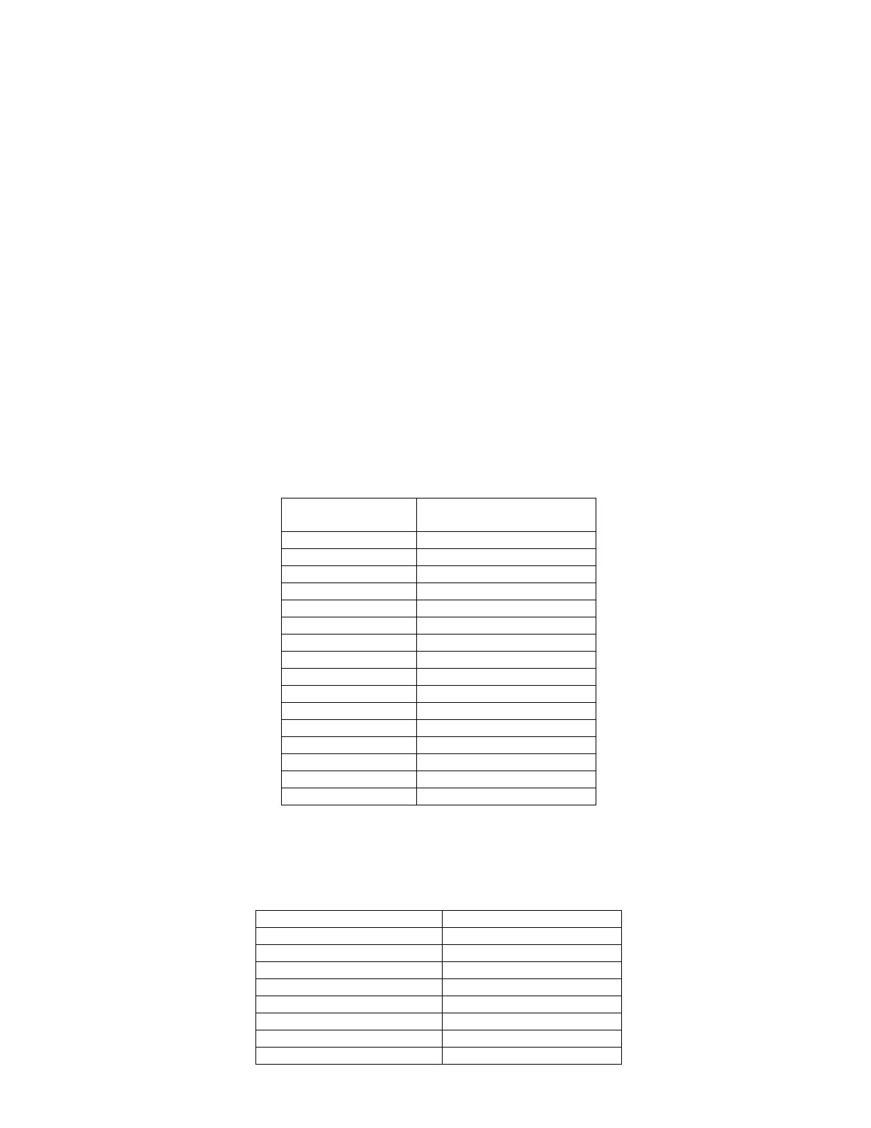
2.3.5.1 Message coding
Message ASCII Code in
hexadecimal
N 4E
E 65
X 78
t 74
20
O 4F
n 6E
20
O 4F
f 66
f 66
20
E 45
x 78
i 69
t 74
Table 5: ASCII message
2.3.5.2 RAM message
RAM Coded message
Address hexadecimal Value in hexadecimal
68 4E65
69 7874
6A 204F
6B 6E20
6C 4F66
6D 6620
6E 4578
6F 6974
 Loading...