BATTERY CHARGER USER’S MANUAL PART- 2: THEORY OF OPERATION
MCEnPC23-REV.2.4 Page 10
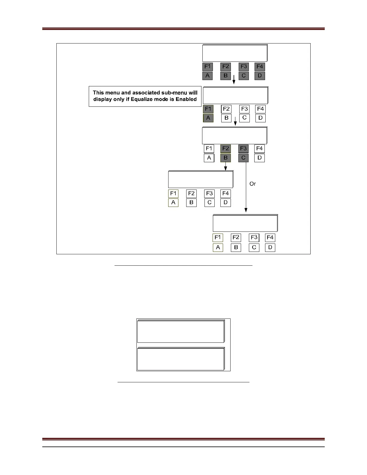
120.5V
10.2A
Equalize
MODE
EqFlt
Ok
Next
Exit
P
Float
Exit
Eq
Float
Float
Exit
Eq
Equalize
Float
Exit
Eq
Figure 9 : Enabling Manually Float or Equalize Mode.
5. AC INPUT VOLTAGE(S) AND CURRENT(S) (OPTIONAL)
If this option is ordered, the AC Input Voltage and Current are displayed on the LCD.
VAC1
136.4V
20.0
120.5V
IAC1
136.4V 20.0
80.3A
Figure 10 : AC Input Voltage and Current Readings.
In case of 3 phase units, the phase voltage and current readings will be scrolling on the LCD as follow: VAC1,
VAC2, VAC3, IAC1, IAC2 and IAC3.
 Loading...