BATTERY CHARGER USER’S MANUAL PART- 2: THEORY OF OPERATION
MCEnPC23-REV.2.4 Page 11
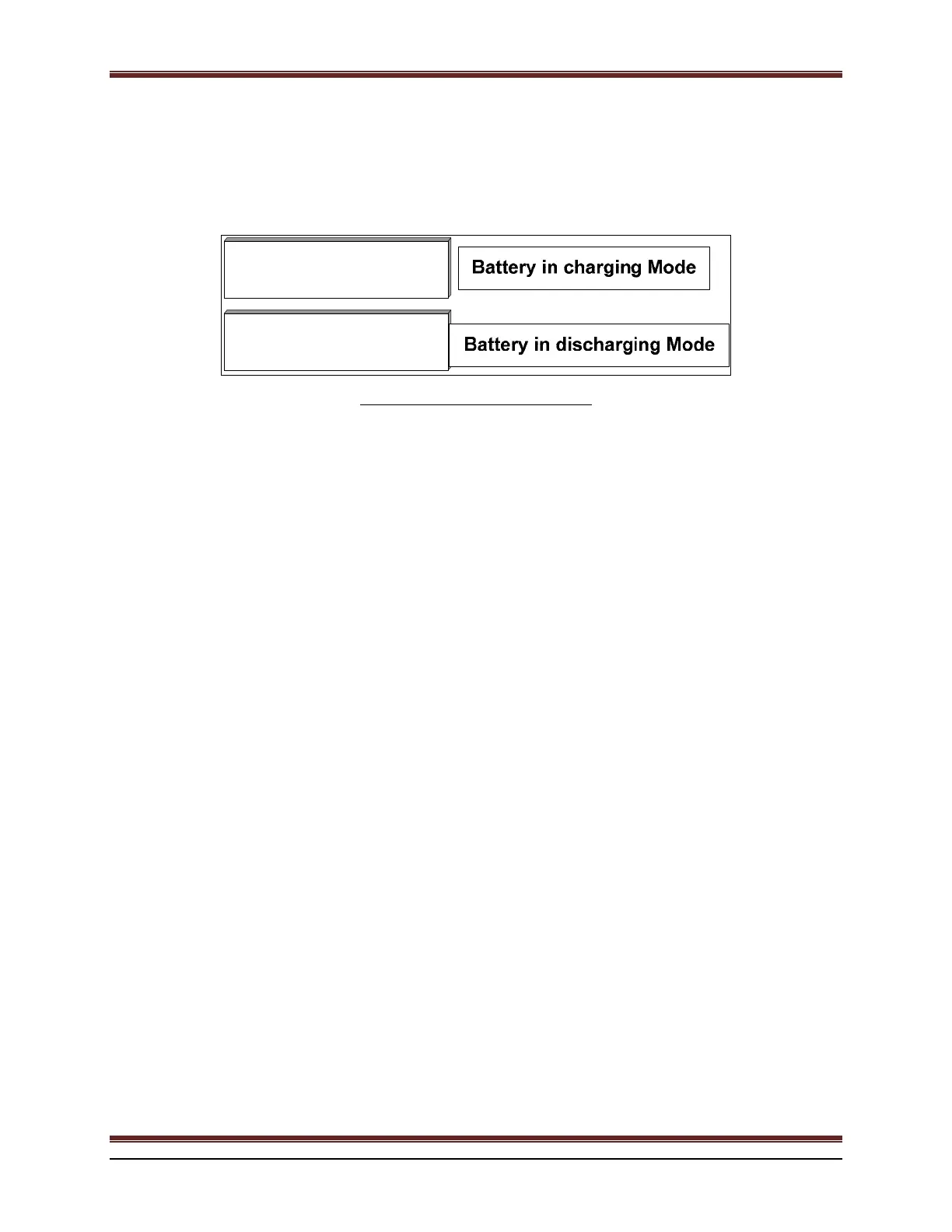
6. BATTERY CURRENT (OPTIONAL)
The current flowing IN or OUT of the battery will be displayed on LCD if this option is enabled. Negative (-) sign
will be displayed in case of battery discharging.
IBatt
136.2V
20.1A
23.3A
IBatt
136.1V
20.0
80.4A -
Figure 11 : Battery Current Display.
7. MENU AND CONFIGURATION PARAMETERS
The battery charger is controlled by a 32-bit Microcontroller
installed on the control board. All parameters are saved
into a EEPROM. The settings are configured into two categories:
1. Charger active parameters such as the alarm settings, O/P voltage and current, etc.
2. Charger active configuration: Temperature compensation, load sharing (if ordered). The calibration settings
are reserved for factory use only.
The battery charger allows users to adjust and visualize the following parameters:
DC Output voltage and current;
Equalize operation mode;
Float operation mode;
Charger current limit mode;
Battery voltage remote sensing;
Alarm adjustments;
Temperature compensation;
Load sharing;
250 events monitoring (date and time stamp are optional);
Reset alarms and relays;
Measures :
AC Frequency.
Rectifier voltage.
Voltage between positive output and chassis.
Voltage between negative output and chassis.
Remaining time for Equalize.
Elapsed time for Equalize.
Charger temperature.
Battery temperature (optional).
Battery Voltage discharge test (optional).
Battery current discharge test (optional).
Battery discharge time (optional).
Relay test.
LCD contrast adjustment.
 Loading...