Page 16 of 39 Rev. 13
Table 6: ASCII message
2.3.5.3 Signal and message association
To link message #2 to signal #3, send (0010 in binary) to bit 7,6,5 and 4 respectively into the register (58H hex), (Refer
to Note 5).
2.4 OTHER SETTINGS
Please contact the manufacturer for further instructions.
3. DNP V3.00
3.1 INTRODUCTION
The purpose of this section is to describe the specific implementation of the DNP3 within PCOM communications
interface. This document, in conjunction with the DNP3 Basic 4 Document Set, and the DNP Subset Definitions
Document, provides complete information on how to communicate with PCOM Communications Interface via the
DNP3 protocol. This implementation of DNP3 is fully compliant with DNP3 Subset Definition Level 2, contains many
Subset Level 3 features.
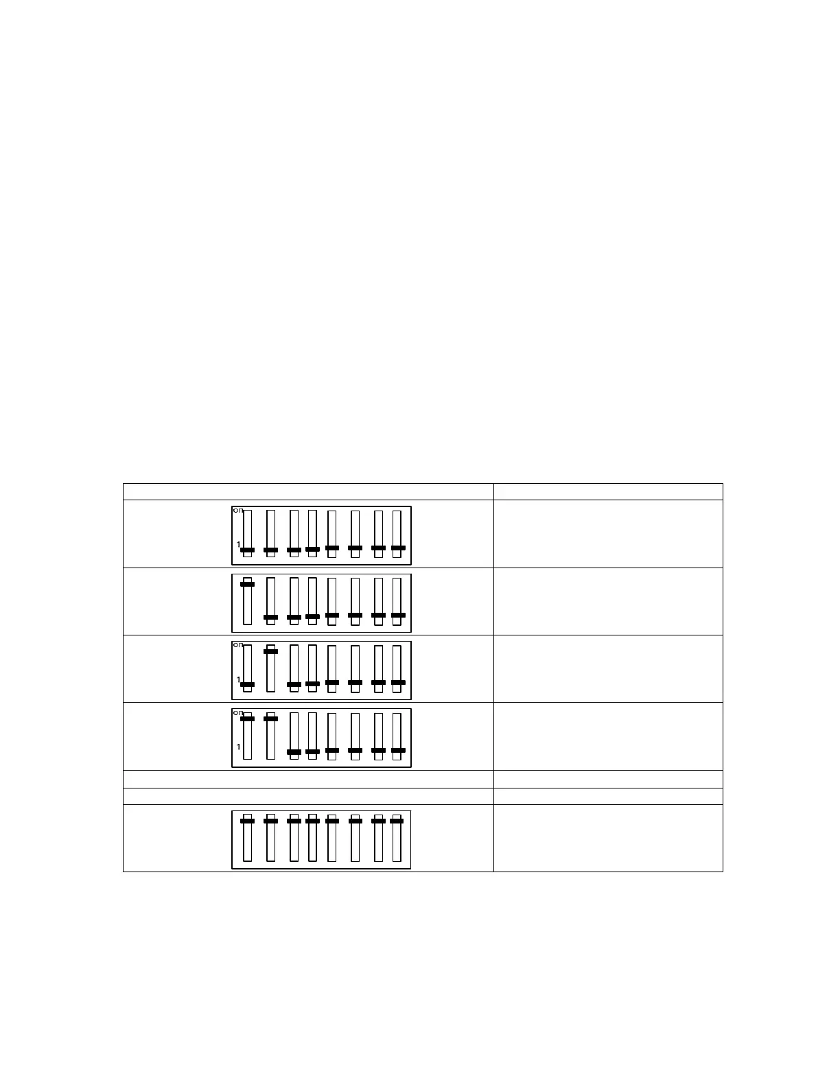
The address of PCOM card is configurable on board as a multiple of 10, from 10 to 2550, and selected with SW3 switch
(see Table 7). The default address is “10“.
Position of SW3 Slave address
0
on
1
10
20
30
. .
. .
on
1
2560
Table7: address of communication according to the position of the SW3 switch
3.2 DEVICE PROFILE
The following table provides a “Device Profile Document” in the standard format defined in the DNP3 Subset Definitions
Document. While it is referred to in the DNP3 Subset
Definitions as a “Document,” it is only a component of a total interoperability guide. This table, in combination with the
following should provide a complete interoperability/ configuration guide for the PCOM Communications Interface:
 Loading...