APX 525/625 Generator Revision C Pre-Installation
©
2005 Del Medical Imaging Corporation
7/5/2005 Page 88
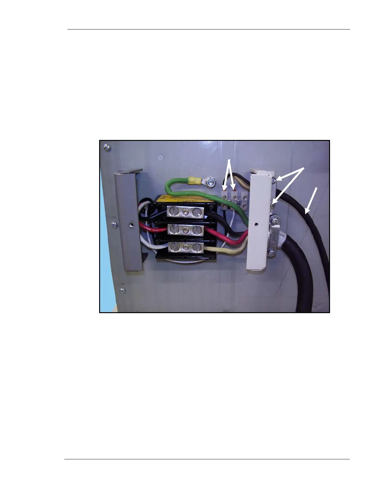
19. Loosen two stress relief clamp screws (1 Fig. 11).
20. Insert the end of the secondary cable (2) (P/N 126-0211G1) into the stress
relief clamp until the black insulation on the cable is within the stress relief
clamp as shown in Figure 11.
21. Tighten stress relief clamp screws.
22. Connect white and black wires to TB2 as shown below. It does not matter
which color wire goes in which position.
Figure 11. Secondary Cable Upper Connections
23. Reattach rear cover.
1
2
TB 2