EasyManua.ls Logo

Vaillant MultiMatic 700/2 - Page 87

Vaillant MultiMatic 700/2
112 pages
Print Icon
To Next Page IconTo Next Page
To Previous Page IconTo Previous Page
Loading...
multiMATIC 700/2
Notes
10/2015 83 Training 0020228700_00
Target flow temp.
Service information
Enter contact details
Service date
Enter code
Installer level
System configuration
Screed-drying function
Change code
Sensor/actuator test
Fault status
Water pressure
Frost protect. delay
OT constant heating
Control modules
Configure heat. circ.
Status
Current flow temp.
System
Type of circuit
Day temp. heating
Set-back temp. heat.
Pump status
Room temp. mod.
Max limit outs.temp.
Heating curve
Auto Off mode
Heat generator 2
Mixer status
HEATING CIRCUIT 1/2/3
*1
System status
000
Level 3: Installer level
Adaptive heat. curve
Heat generator 1
Status
Current flow temp.
Cooling possible
End OT cooling
Min. cool. fl. tgt temp.
1
Current room air hum.
Multi-funct. output 2
*7
Additional module
*7
System diagram
Aux. heater output
Room temperature
System diagram config.
Config.: VR 70 addr. 1
MA VR 70, addr. 1
*2
Status
Excessive temp.
Maximum temperature
Minimum temperature
Dew point monitoring
*9
Status ext. heat dem.
*6
ZONE 1/2/3
*1
Zone activated
Zone assignment
Zone valve status
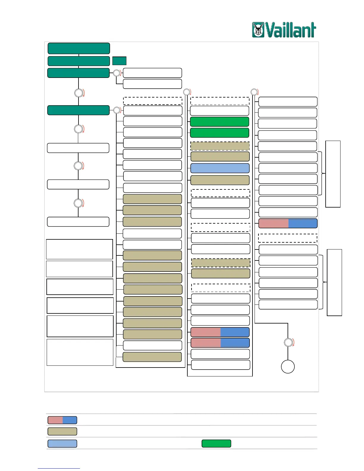
Displayed if "Zone activated"
= "Yes" is selected
System flow temp.
*2
Automatic cooling
Source regeneration
Hybrid manager
DHW bivalence point
*7
Heat. bivalence point
*4
Alternative point
*4
T. emergency mode
Auxiliary heater type
*5
Energy supplier
*7
Auxiliary heater for
*7
*4
Displayed if "Hybrid man-
ager" = "Bivalence point" is
selected
*5
Displayed if "Hybrid man-
ager" = "triVAI" is selected
*6
Displayed with VR 70 = 1, 2,
5
*7
Displayed in conjunction with
aroTHERM, flexoTHERM
*9
Displayed if "Room temp.
mod" = "Temp. mod.“ and
"Zone assignment" = "VRC
700" or "VR 91"
Offset dew point
*9
Current temperature
Current dew point
*8
Status
*7, *8
Additional module
*7, *8
*8
Only displayed if a second
heat generator is not con-
nected
Multi-funct. input
*7
Start OT cooling
Buff. cyl. offs.
= Displayed in conjunction with geoTHERM 3 kW, aroTHERM, flexoTHERM
= Displayed for heating circuit 2 and 3 or for heating circuit 1 with VR 70 = 3, 5, 12
= Displayed in conjunction with aroTHERM
*2
: = Displayed with VR 70 = 1, 3, 6
*1
: Two with VR 70 = 1, 5 / three with VR 71
= Displayed in conjunction with VR 70
Displayed if "Cooling possi-
ble" = "Yes" is selected

Table of Contents

Related product manuals