3-9Valco Cincinnati, Inc.
MC075 - MCP-4 Control Unit Section 3 - Basic Features
MCP-4 Valve
Driver
Instructions
Wiring Configurations
for Triggering the
Valves
One of three wiring configurations can be used to trigger the valves. Chose
the one that best fits the needs of your system. Detailed instructions for each
configuration are given in the next section.
Warning!Warning!
Warning!Warning!
Warning! The triggering device used
must must
must must
must be configured to
output
only 24VDConly 24VDC
only 24VDConly 24VDC
only 24VDC. If the control unit has a spike, it
will damage the input circuit for the scanner.
Wiring the Scanner Cable
1. Make sure the MCP-4 power switch is OFF and the unit is
unplugged.
2. Cut the female connector off of the Scanner 1 cable.
Warning!Warning!
Warning!Warning!
Warning! Disconnect all power and input signal wiring before
attempting to install or replace any part of the glue
system. Otherwise, personal injury or death may occur!
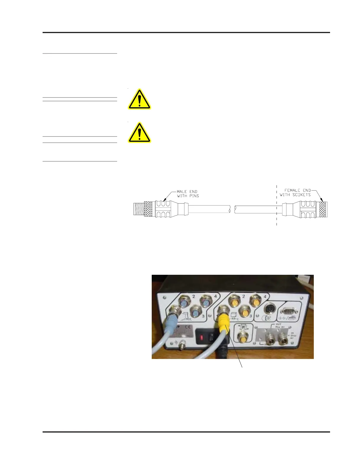
3. Plug the male connector (on the Scanner 1 cable) into the
Scanner 1 input port on the back of the MCP-4 Control Unit.
Cut off and discard the
female end of the cable.
Scanner cable (male connector) plugged
into the Scanner 1 input port
4. Carefully strip the scanner cable jacket back and strip the
individual wire insulations about 0.25 inch.
5. Wire the modified scanner cable according to the Wiring
Diagram (next page).
 Loading...