Technische Änderungen vorbehalten Technical details subject to change
(1-8) - 5TU00-0736-5107120 0609
Montageanleitung
Installation Instructions
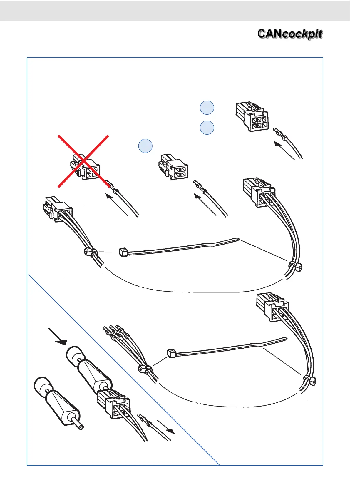
B: für Kabelbaum Master - Slave / for wiring harness master - satelitte
C: für Kabelbaum Slave - Slave / for wiring harness satelitte - satelitte
Ausstoßwerkzeug (Pos. 14)
Push out tool
Die Kabel (Pos. 15, 16, 17) je nach Belegung in den 4poligen
(Pos. 11) / 6poligen Stecker (Pos. 12) einstecken. Die
Kontakte müssen hörbar einrasten.
Insert the cabels (Pos. 15, 16, 17) into the 4-pole (Pos. 11) /
6-pole connector (Pos. 12) according to connector pin alloca-
tion. The pins must engage with an audible click.
B2
B3
C2
rot
red
schwarz
black
gelb
yellow
rot
red
schwarz
black
gelb
yellow
rot
red
schwarz
black
gelb
yellow