At this point it’s easy to
realize which Satellites
still have not the right
Symbols assigned. By
use of the ICON Editor
these Symbols are now
created and can be
assigned to the
appropriate device.
Up to now basic configuration values like Name, Symbol, Unit,
trailing Digits and Hysteresis values have been defined. This
parameter setting is dedicated to present the individual device
values in the Master Display. After creation of the missing
Symbols plus the assignment to the correct device the next step
is to define the In/Out characteristics for each device. Doing this
implies that for each device, Master, Satellite or Display, the
right Sensor is assigned and configured.
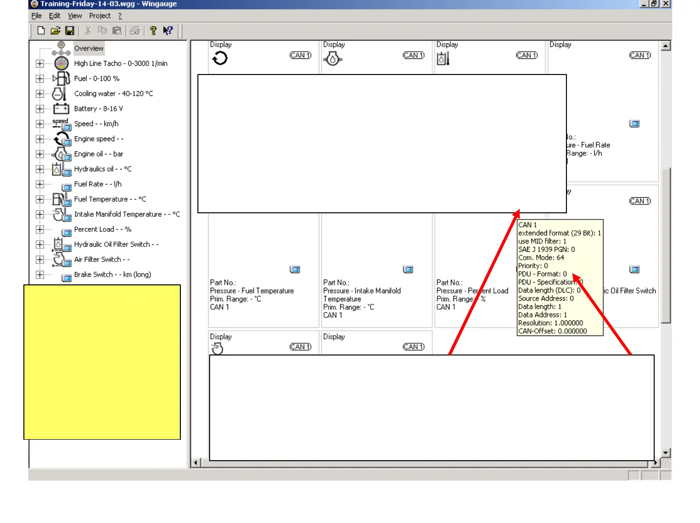
Searching for Satellites or Displays which haven’t received the full
configuration is made easier when pointing with the mouse pointer to the
“CAN 1” sign on the upper right corner of each device in the
"Configuration-Window" . This opens up a window with all the CAN
Parameter settings. A device is not configured when essential parameters are
preset by "0".
June 2009
Training WinGauge Software
page 25