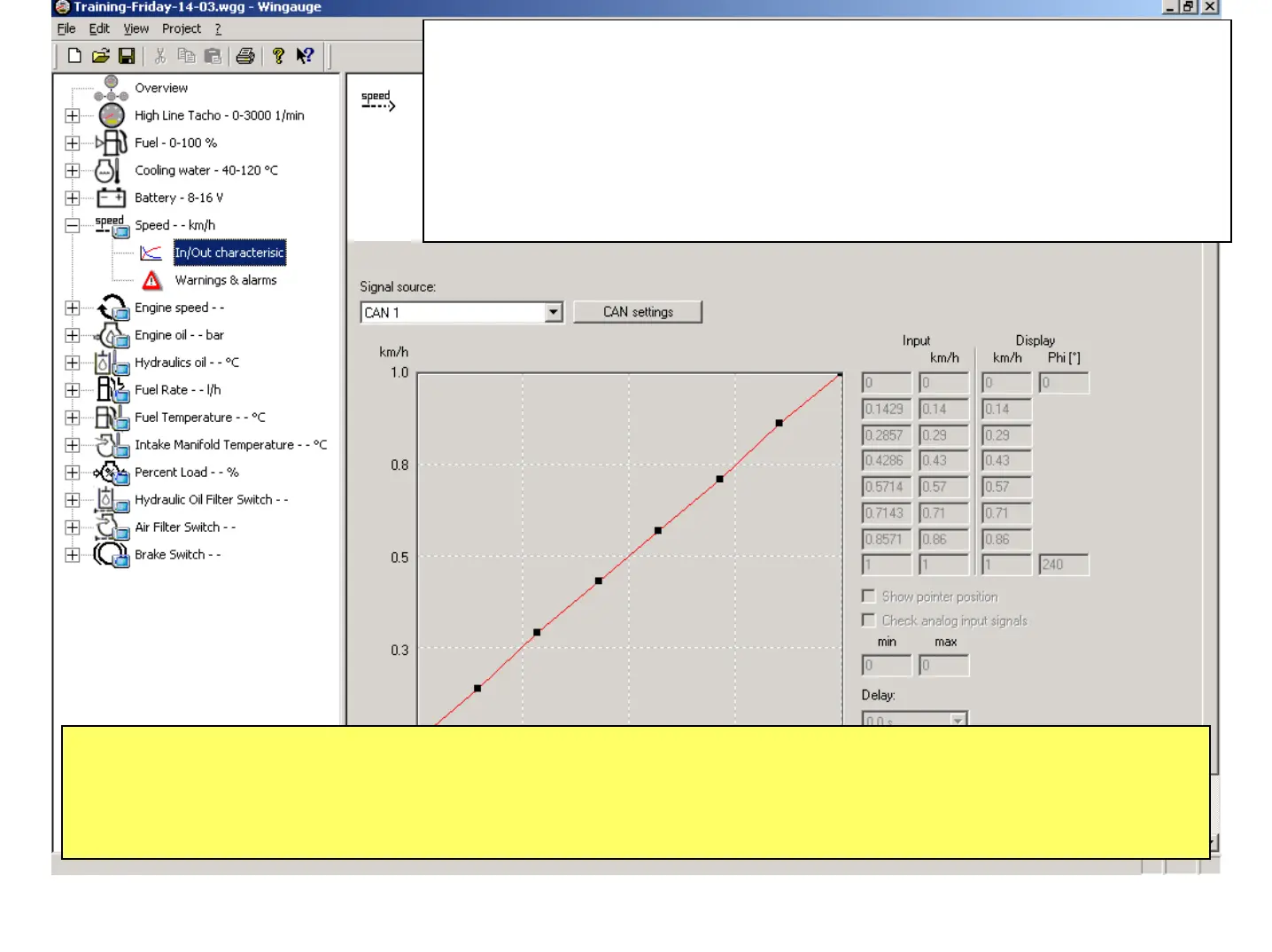
The dialog "Add Display" has preconfigured the "Speed" device. E.g. the
Signal Source is been presetted with "CAN1" and the Curve is defined as
linear with standard Values. For the definition of the Prime Range those two
values have to be corrected. However it’s more important for Satellite than for
Display devices, as Displays don’t really have a upper limit, but are showing
their Values in the LCD Display of the Master Device. The first step here is to
select as Signal Source the Frequency input 1 (0 – 40 kHz).
Typically the required Parameters for this part of the Configuration are predefined as they depend very much on
the physical Instruments like Signal Source, Switches, Sensors… which are connected in the System. Those
Parameters may be taken from the Hardware Configuration. It is recommended to have these Characteristic
Values of the Sensors available before the Software Configuration via WinGauge is started.
June 2009
Training WinGauge Software
page 33
 Loading...