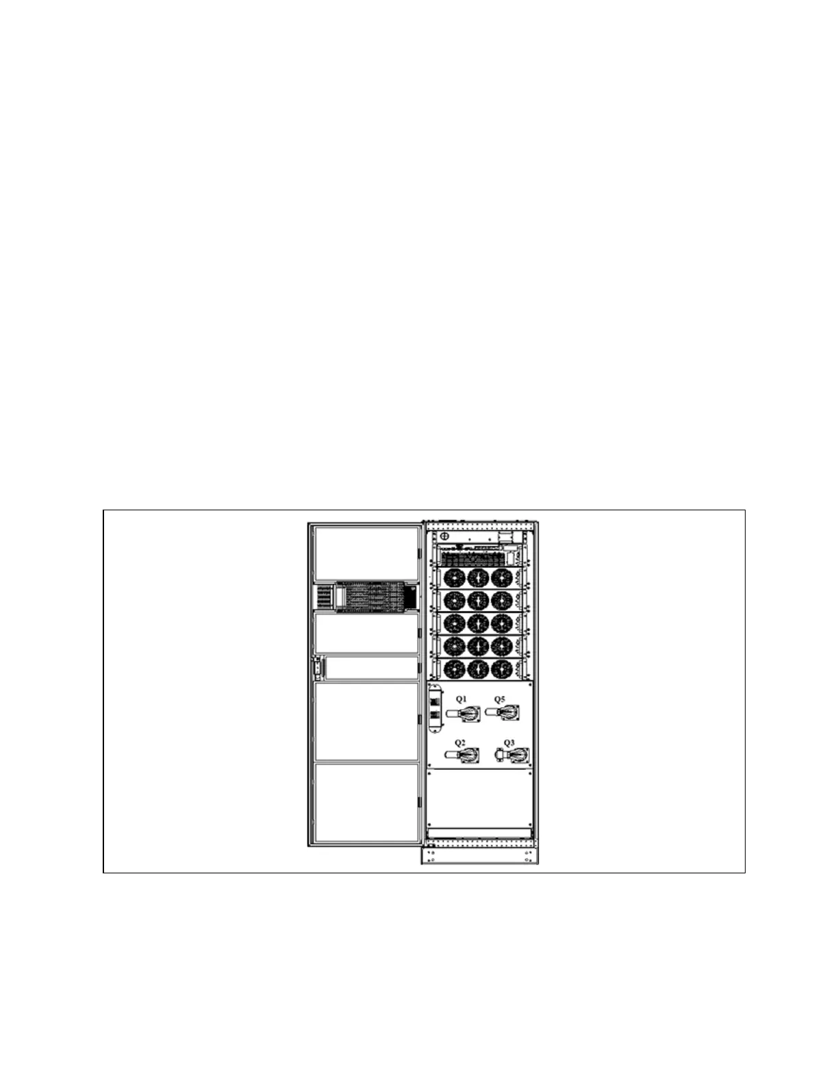
6.1.2 Power Switch
Opening the front door of the UPS cabinet reveals the power switches, as shown in Figure 6.1 below, including:
Q1: Rectifier input switch, which connects UPS to the main circuit power.
Q2: Bypass input switch, which connects UPS to the bypass.
Q3: Maintenance bypass switch (With error-proof operation buckle), which supplies power to the load when UPS is being
maintained.
N O T E: If the UP S system consists of m ore than tw o paralleled UP S m od ules, do n ot use the internal
m aintenance b ypass sw itch.
Q5: Output switch, which connects UPS output to the load.
N O T E: Q1, Q2, an d Q5 are optional while Q3 is standard .
N O T E: For U P S m ainten ance an d dust rem oval, please in stall an d other sw itches (including external
m aintenance b ypass sw itches) w hen u sing Q3.
N O T E: The in put-output N line inside the UPS is inter-operable. If the external N line is not
disconnected during maintenance, please pay attention to safety.
Figure 6.1 U P S pow er sw itch
6 Single UPS Operation Introduction
95
Vertiv™ Liebert® APM Plus User Manual