4.1.2 Maximum Steady State AC and DC Currents
The power cable must be selected according to the current and voltage values in Table 4.1 below as well as the local wiring
regulations, and take environmental conditions (temperature and physical media) into consideration, then refer to Table 3B in
IEC 60950-1.
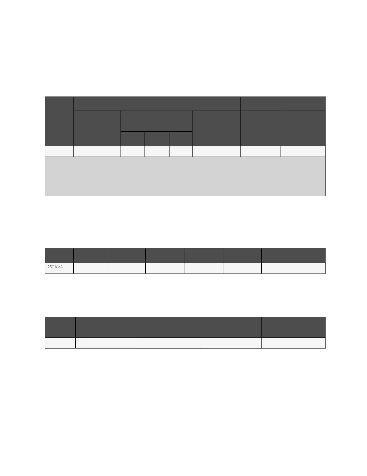
UPS
po w er
(kV A )
Rated c urrent (A ) Bus stu d bo lt/nu t specificatio n
M ax. inp ut
cu rren t
1,2
O utput/bypass curre nt
2
at fu ll
load
Battery d ischarge
3
cu rren t (+ , -, N ) a t
m in. b atte ry vo ltage
Input, b atte ry,
ou tput,
by pass /PE
cable
Recom m en ded
torq ue (N m )
38 0 V 40 0 V 415 V
250 kVA 496 380 363 348 903 M12 39 ± 10%
Note:
1. Max. current of low voltage (176 V) for rectifier input at full load.
2. Non-linear load (like switch power) affects the design of output and bypass neutral line.
3. The discharge current at EOD point (voltage is 9.6 V) calculated by 30-block battery.
Table 4.1 M ax. steady state A C and DC currents
4.1.3 Recommended CSA of UPS Cable
The recommended CSA of the single module cable is listed in Table 4.2 below.
M ode l Input O utpu t Bypass N eu tral line Ea rth ca ble Battery
250 kVA 2*95 2*70 2*70 2*95 95 See Table 7.4 on page125
Table 4.2 R ecom m ended CSA of the U P S single m odule cable (unit: m m
2
, am bient tem p eratu re: 25
°C )
4.1.4 Selection of UPS I/O Switch
Table 4.3 below shows inbuilt switch assembly capacities.
M ode l
Rectifier input sw itch
(op tion al)
Bypass inp ut sw itch
(op tion al)
O utput sw itch (o ptio nal)
M ain tenance b ypass sw itch
(stand ard)
250 kVA 500 A (3P), isolating switch 500 A (3P), isolation switch 400 A (4P), isolating switch 400 A (3P), isolating switch
Table 4.3 Inb uilt U P S I/O sw itch capacity
N O T E: The sw itch of UPS m odule is an isolation sw itch by d efault. T o prevent U PS fault from
spreadin g to the u pstream of custom ers, it is recom m ended to in put a sep arate switch to the UP S
according to the cu rrent value in T able 4 .1 above.
N O T E: W e recom m end configuring Vertiv BCB box for the U P S with external batteries. If BC B is not
selected, please select battery switch according to B C B param eters show n in 9.5 B C B Box.
4 Electrical Installation
29
Vertiv™ Liebert® APM Plus User Manual