7.8 Design of Battery Room
No matter which type of installation system is adopted, the following items shall be paid special attention to (refer toFigure 7.2
below).
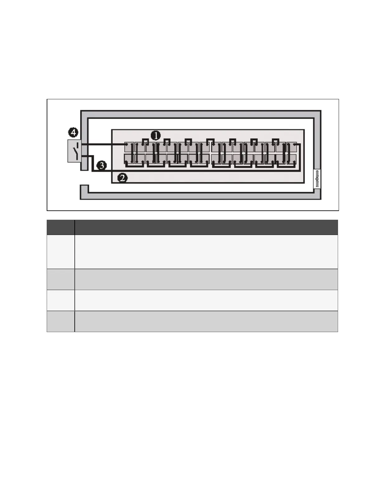
Figure 7.2 D esign of battery room
N o. Descrip tion
1
Layout of cells
No matter which battery installation system is used, the battery shall be located in a matter that it will not contact two naked live parts with
the potential difference over 150 V at the same time. If it is unavoidable, insulated terminal shield and insulated cable shall be used for the
connection.
2
Workbench
The workbench (or pedal) must be skid-proof and insulated, and at least 1 m wide.
3
Wiring
All the wiring distances shall be minimized.
4
BCB
The BCB is generally installed in the wall-mounted box near the battery.
7 Battery
119
Vertiv™ Liebert® APM Plus User Manual