8.2.5 Parallel Cable
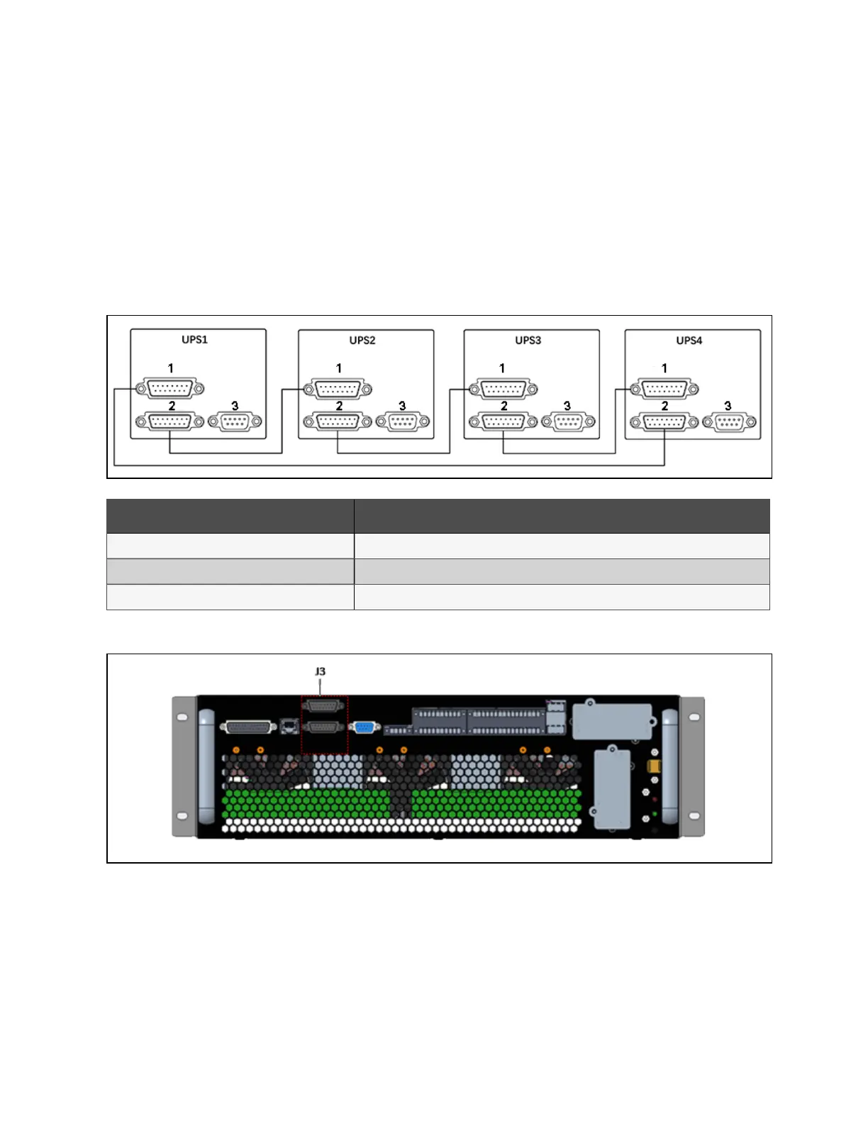
Shielded and double-insulated parallel cables available in lengths 5 m, 10 m and 15 m must be interconnected in a ring
configuration between the UPS modules, as shown in Figure 8.2 below. Method: Connect a module parallel cable from its
PARA1 port to the PARA2 port of another module. Follow this method to connect other parallel cables.
The parallel port J3 is provided on the front panel of the bypass control module, as shown in Figure 8.3 below.
The ring connection ensures the reliability of the control of the parallel system. Be sure to verify the reliable cable connection
before starting up the system!
Figure 8.2 Parallel sig nal cables connection (Parallel system )
N o. Descriptio n
1 PARA1
2 PARA2
3 LBS
Figure 8.3 Location of parallel port J3 on b yp ass control module
8 Parallel System and LBS System
131
Vertiv™ Liebert® APM Plus User Manual